• The move to the new server is done. There are some software and database maintenance updates in process. This has us passing the hat around to help out. We appreciate any donations. Seriously, even a dollar helps. The payment page may be found here - https://www.audiokarma.org/support.html

KLH Model Twelve, Five Pounds of Capacitors into a Four Pound box.

FireGuruMN

Active Member
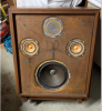
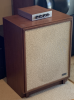
I got these off CL last Fall. $200.00 since you asked. Had to hide them in garage until the time was right. You've all been there.
upload_2020-4-20_10-53-48.png
I still need to refinish the cabinets. They have a bit of a milky look to them and I like crisp grain. The contour box (crossover) has nice crisp grain and that is what I am heading for.
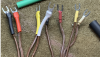
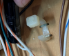
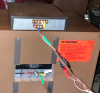
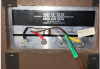
First step, rebuild the cables that connect the crossover to the cabinet. Only one set of original space connectors was still in place:
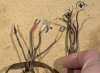
upload_2020-4-20_10-58-53.png
Original and finished:
upload_2020-4-20_11-1-41.png
I crimped and soldered all the space connectors. I never trust crimping alone for things I care about.
One conductor does have a different type of metal so you can identify the strands:
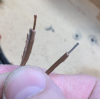
upload_2020-4-20_11-3-30.png
But if you don't have an ohm meter on your bench you shouldn't be here.
The finished cables:
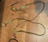
upload_2020-4-20_11-4-45.png
The green heat shrink is to keep the cables from separating past the point I want them separated but really these are so stuck together it is not needed. And yes, I replaced the original connectors also. Call me anal.
On to the crossovers. First step is to add some extra wood to the place where the screws dig into the wood. The originals just barely hit the edge of the plywood and did not grab well:
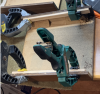
upload_2020-4-20_11-7-24.png
No rocket science here.
Continued. . .
 
Register to hide this ad
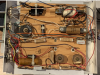
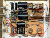
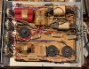
Inside one crossover:
upload_2020-4-20_11-11-5.png
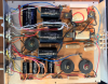
And the other:
upload_2020-4-20_11-11-34.png
It's like one of those puzzles where you try to find everything that changed in the pictures. I'm guessing these crossovers were not made the same day, or the same year, in the same factory, by the same technician or whatever. Maybe they ran out of some brand of capacitor and had to find replacements. The 16uf in the middle of the lower crossover was replaced with two dual 4uf capacitors wired in parallel in the upper picture to get the same value. The two big red 50uf caps at the top were replaced with two smaller 47uf caps at the bottom. That might have been a repair done at some point if you look at the tie wraps/staples. But enough CSI, time to rip them all out and put in new.
I did some investigation into how this crossover was wired. But I could not figure out what was going on inside the wafer switches and I discovered that if I use a 30uf film cap along with a 17uf film cap I could fit them all inside the case. Well, almost, read on.
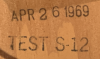
Date code:
upload_2020-4-20_11-20-30.png
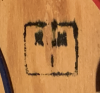
Quality control stamp that need some quality control of its own:
upload_2020-4-20_11-21-7.png
A little cleanup is in order first:
Remove the knobs. Turn them up or down to get to the set screw in the back. Easiest to start at the low frequency end and move to the high frequencies.
upload_2020-4-20_11-31-2.png
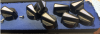
I think someone used velcro to attach these to the back of the unit to raise the WAF (wife acceptance factor) but left them face up to gather dust. This is AFTER the first round of cleaning.

upload_2020-4-20_11-32-49.png
Soak the knobs in soapy water while working on other things and all the goo will be gone.
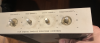
The face plate comes off if you remove the two nuts on the high and low frequencies. IT IS VERY THIN METAL so don't bend it. Soapy water will clean it right up. Don't use anything abrasive. Mine were bent a bit so I carefully flattened them out. In the end I wanted the top and sides bent back a bit so they would fit tight against the wood crossover cover. More on that later.
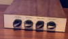
Here is the end product (still need to do the wood finishing)
upload_2020-4-20_11-42-37.png
Continued . . .
 
OK, you're anal. You're doing a nice job there. Keep the thread going here. I'm in Excelsior, wanna see those when you're done. I almost bought a pair of those once, but my Fives are close without the bulk.
 
Ok, on to the main event, magically putting five pounds of caps into the 4 pound box:
upload_2020-4-20_12-14-17.png
You will notice one resistor per speaker also. I saw a bunch of threads where one of the resistors in the woofer circuit melted, burned, (fell over and sank into the swamp) whatever. Apparently all the resistors are 5watt resistors. That is just fine for the tweets and mids but not adequate for a heavily used woofer. So I upgraded just that one resistor to a 10 watt. Feel free to upgrade all of yours but it is not necessary.
I guess it is not appropriate to put specific part numbers and links in these emails. whatever. You will need these capacitors:
Counts PER CROSSOVER:
Qty 2 of 47uf (one xover was 47uf and the other was 50uf but 50uf does not existing in the real world)
WARNING if you are using film capacitors make sure you have space. I found that I could fit a 30uf and 16uf in one crossover but later found out that the crossover with the red caps also had a thicker wood base plate and the 30uf would not fit. Well, it fit if you forced it. I forced it. More later. Maybe you could get 24uf and 24uf or some other values. Figure it out on your own. If you are getting bipolar electrolytics you will not have any space issues and you will get to do it all again in 10 or 20 years. Just saying.
Qty 1 of 16uf
Qty 3 of 4uf
Qty 1 of 3uf
Qty 1 of 5ohm 10watt resistor.
All the other inductors and resistors are fine unless you want to replace them to make yourself feel good inside.
The existing capacitors are held down like this:
upload_2020-4-20_12-24-58.png
Kinda neat, saves fancy mounting stick ons that never stick on and is cheaper than the screw down tie straps. The crossover with red caps had strapping tape holding most things down instead of tie wraps. The adhesive was all dried up but the tape was stapled down also so that made for a lasting connection. Personally I hot-glue everything down. Whatever makes you happy.
Here is what one crossover looked like when I was done:
upload_2020-4-20_12-29-53.png
Some notes:
The resistor in the top right is the one I replaced.
The inductor in the top right was shifted right about 1/2 inch to make room. I don't know that I needed it in the end but its done.
I put heat shrink over most every connection I could. You never know when something will break free and the less exposed conductors the better.
Any lead from a capacitor that can move should be hot glued down. If they are free to move the wires will wear out from continued bending.
Things I did wrong:
Temporarily re-mount the two wafer switches you took out to clean the faceplate. The leads on those switches are barely long enough to reach and when I rerouted them to fit the new capacitors in place they were not long enough and ain't nobody got time for that.
The solder lugs on the wafer switches are delicate, flimsy, substandard [put other words here]. One broke off when I was dinking around. I was able to solder it back onto the switch but it could have been a show stopper.
I used some wire from the capacitors that I removed to extend the leads on some of the new capacitors. At least I know the wiring will be period with the other wiring!
Here is the other crossover:
upload_2020-4-20_12-38-12.png
Can you see what changed?
The small caps on the bottom are in a different order. Nope, you never would have gotten that one. This way I did not have to extend as many leads. See honey, I can learn.
The big mistake in this picture is the 30uf cap in the top left. On the other crossover I had a 16uf in that position. But for whatever reason the 30uf would not fit on the end by the inductor so I swapped it. This is a problem because the wood cover has an angled wood reinforcement piece that hits there. So I have to pry off the hot glue (hot glue is very sticky) and shift it a bit downward. But then it was still hitting the top of the wood case by about 1/8th of an inch. I was able to get the cover on by using a bit longer screw and it looks fine but I'm not proud of myself.
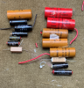
Here is everything I took out:
upload_2020-4-20_12-43-17.png
Quite a variety of manufacturers. I did measure some of the values. Many did not even read as capacitors. Some had good capacitance values but huge ESR. They all had to go.
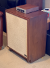
I think the styling of the speakers if pretty simple but appropriate for the period.
upload_2020-4-20_12-45-47.png
Many people complain about the low WAF but if you see the 4435's in the background you can see that the Model Twelves do have a higher WAF than some products. I have Dahlquist DQ10's also which have a unique look and in my case a very high WAF. Those might be headed to the living room! But the geek factor of having a separate crossover sitting on the top raises the value in my book.
More pictures to was AK storage space:
upload_2020-4-20_12-49-21.png
Continued. . .
 

Attachments

  • upload_2020-4-20_12-49-43.png
    upload_2020-4-20_12-49-43.png
    731.6 KB · Views: 12
Do you see the "12" tagged on the face. Like they didn't know?
upload_2020-4-20_12-53-8.png
Anyone know what the 25.6 is marked on the woofer?
And why does the crossover say "300 ohms" on the input terminals? My meter said 6.5 ohms when I was all finished. Can the impedance be that much different from the resistance?

After thoughts:
Spray de-oxit on the wafer switches. I held mine face down and sprayed the back sides of them. Use some paper towels or it gets everywhere. The goo will work down into the switch through the holes. Then work each switch 20 or so times. You will feel them loosen up but keep going until you get to 20 or more.

Oh, and how do they sound you might wonder?
Well as I do with speakers, I finish one and then setup the finished one on the left side and the original one on the right side and use the balance control to compare. Assuming I have a mono source and both my ears are equally shot at my advanced years. Turned 55 and I can't go to Perkins to order off the senior menu cause of this Covid stuff.
There was really no comparison here. The untouched speaker did not even have ANY OUTPUT in the tweeters of mids. Nothing, Nada, Zippo.
After doing both speakers I set everything up again. I used the balance to ensure both speakers sound the same. That is important in case there is a bad driver or something. After than I played music. These speakers sound great! And I mean great period. Not "great for 1969 speakers". Nice clear midranges and good high end. The bass is smooth. KLH did everything he could go squeeze base out of that size driver but a modern 12" or 15" driver will still put it shame. I have to imagine the first time people heard these back in '69 they were amazed at the low end. And probably at the overall quality of the sound in general. They were a milestone.

It does seem to take a lot of power to drive these. That's a bit surprising given that this was still back in the tube era mostly. But I suppose 20watts will make them sound fine.

One of these days I will line up AR3a, CS-99, DQ-10's and these speakers and have a proper shoot out. My back will hurt that day.
 
I believe the 25.6 on the woofer is probably the resonance frequency. I have two 23s, one of which has 25.3 written on it. (They are not exactly a pair since I found each separately and the drivers are clearly from different runs.)
 
Cool, that's even geekier than I expected. I was going for some sort of weight or dimension.
Shows what half an MIT education will get for you. I was googling some of Henry Kloss's history.
upload_2020-4-20_13-24-2.png
"Research and Development Corporation". Woohoo. Almost as good as Crown's "Laboratory Power Amplifier". Didn't Scott have something like that on their early tube stuff?
Or early Bang and Olufsen "By Appointment to the Royal Danish Court". Lots of horn tooting going on in the early days of Hi-Fi.
 
Well, in the case of KLH (and AR), R&D was actually a significant part of what they did. Much less was known back then about how audio equipment worked (and with the transition from tubes to solid state, and from large box speakers to acoustic suspension, what was known pretty well was not necessarily as relelvant as it used to be), and there was still a great deal of experimentation in cone pulps and magnetic structures and the like. Kloss, who was an inveterate tinkerer apparently had a room full of Waring blenders, all running different combinations of fibers and stuff for woofer cones.
And I believe that the 'By Appointment to the Royal Danish Court' was actually a technical qualification by the government for quality standards in various product categories. The british have something almost exactly the same - we used to get marmalade that had a very similar phrase, which eludes my aging brain right now.
 
Nicely done! I had the same experience with the Model 12s I used to own, it definitely takes some trial and error to make everything fit. Some of the caps I got were too large in diameter so I ended up having to mill pockets into the plywood :eek:

That 300 ohms does seem high, but with a crossover that complex I guess anything is possible! Extra power really does wake them up, I used a Heathkit AA-1640 with mine and the improvement over lower powered gear was night and day.
 
I was driving these with a Yamaha CX-A5000/MX-A5000 so I had plenty of power. I will eventually hook them up to a tube amp and see how that sounds. That is one of my concerns about the 300ohm marking on the input terminals. Tube amps would not be happy with that. At least none of mine.
 
Nicely done!

re: SPL: it's a sealed box. I don't know about newer stuff, but the old ones just took more power.
 
Congratulations on your restoration efforts!!
I got my 12's about a month ago but no original drivers and the crossover has been modified to be used without the control box. Basically I have just the cabinets. Whatever was done works as they sound great.
 
Inside one crossover:
View attachment 1838117
And the other:
View attachment 1838118
It's like one of those puzzles where you try to find everything that changed in the pictures. I'm guessing these crossovers were not made the same day, or the same year, in the same factory, by the same technician or whatever. Maybe they ran out of some brand of capacitor and had to find replacements. The 16uf in the middle of the lower crossover was replaced with two dual 4uf capacitors wired in parallel in the upper picture to get the same value. The two big red 50uf caps at the top were replaced with two smaller 47uf caps at the bottom. That might have been a repair done at some point if you look at the tie wraps/staples. But enough CSI, time to rip them all out and put in new.
I did some investigation into how this crossover was wired. But I could not figure out what was going on inside the wafer switches and I discovered that if I use a 30uf film cap along with a 17uf film cap I could fit them all inside the case. Well, almost, read on.
Date code:
View attachment 1838123
Quality control stamp that need some quality control of its own:
View attachment 1838124
A little cleanup is in order first:
Remove the knobs. Turn them up or down to get to the set screw in the back. Easiest to start at the low frequency end and move to the high frequencies.
View attachment 1838130
I think someone used velcro to attach these to the back of the unit to raise the WAF (wife acceptance factor) but left them face up to gather dust. This is AFTER the first round of cleaning.

View attachment 1838131
Soak the knobs in soapy water while working on other things and all the goo will be gone.
The face plate comes off if you remove the two nuts on the high and low frequencies. IT IS VERY THIN METAL so don't bend it. Soapy water will clean it right up. Don't use anything abrasive. Mine were bent a bit so I carefully flattened them out. In the end I wanted the top and sides bent back a bit so they would fit tight against the wood crossover cover. More on that later.
Here is the end product (still need to do the wood finishing)
View attachment 1838137
Continued . . .

looks like each crossover is different.

Please note that you add capacitors in parallel : so 4uf + 4uf = 8uf, not 16uf.
Capacitors in series: 1/(1/c1+1/c2 ...) ; so if in series they total 2uf.

to make a 50uf put a 47uf in parallel with a 3uf.

Nice restore!!
 
I agree that the numbers are most likely the weight of the cone in grams - its a fast and easy thing to measure, whereas fundamental resonance is more time consuming, and probably not easily compatible with a production line.
 
very nicely done. I always thought those crossovers were way more complicated than they needed to be but good on you for rebuilding them to spec. 5's are lovely speakers & I've always thought of 12's as 5's w/o need for compromise.
WAF, not so much. Mores the pity really as some of the largest boxes make the sweetest sounds.
 
5's are lovely speakers & I've always thought of 12's as 5's w/o need for compromise.
Exactly. I'd love to have a pair of Twelves, more for the visual of them with their external crossovers, but no room, especially with a pair of Altecs in the house. I cherish the Model Fives I restored years ago and listen to them daily.
 
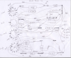
At one point I had a goal of making a schematic but gave up when I did not know what the switching was inside the wafer switches. Here is the point I got to. The jumpers I marked as "R" are just jumpers. At one point I was thinking they might be resistance wire but they are not.
upload_2020-4-21_11-6-20.png
I found another way to improve performance, remove the grills. The grills are a major part of the character of the speakers but they are pretty heavy fabric and there are 2 layers. outside layer:
upload_2020-4-21_11-10-35.png
Inside layer:
upload_2020-4-21_11-11-31.png
Maybe KLH originally designed the frequency response to compensate for the fabric by making the speakers "bright". But some of that brightness is gone now and they sound better without grills (IMHO).
 
Back
Top Bottom