• The move to the new server is done. There are some software and database maintenance updates in process. This has us passing the hat around to help out. We appreciate any donations. Seriously, even a dollar helps. The payment page may be found here - https://www.audiokarma.org/support.html

Klystron tube power supply?

Carbsandcaps

Super Member
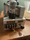
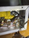
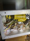
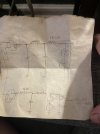
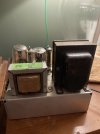
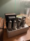
I bought this klystron tube power supply on a whim but I’m not exactly sure how it works. It’s also been tampered with. There’s some heavy wires coming off the transformer just lose inside the chassis I’m assuming they might be heater connections. There’s also a diode on the output connection. I’m wondering if he was bypassing all the voltage regulation and just using it as a transformer. He included this hand drawn schematic. I don’t have a model number but if anyone knows anything about this, I’d sure like to see those oa2 tubes glowing. IMG_2722.jpegIMG_2724.jpegIMG_2726.jpegIMG_2727.jpegIMG_2725.jpeg
 

Attachments

  • IMG_2723.jpeg
    IMG_2723.jpeg
    73 KB · Views: 2
Register to hide this ad
Maybe lose the lower rectifier tube in favor of silicon diodes and monkey with the output resistors to get about -5 to maybe -50. That will get you a bias supply for almost anything.

Also possibly bypass the 2k resistor and the regulator tubes for a high current plate supply. Can parallel the rectifier tubes to bump the hv supply capacity
 
Maybe lose the lower rectifier tube in favor of silicon diodes and monkey with the output resistors to get about -5 to maybe -50. That will get you a bias supply for almost anything.

Also possibly bypass the 2k resistor and the regulator tubes for a high current plate supply. Can parallel the rectifier tubes to bump the hv supply capacity
Im trying to bring it back to original before I do anything. Is the repeller potential a negative voltage?
 
It looks like he bypassed the regulator tubes and went straight out from the rectifiers. It’s got 275vdc out and 0 to -60vdc on the repeller circuit. Then it started smoking so I need a wiring diagram but I have no idea what this thing came out of.
 
Probably bad caps.

Its homebrew, be glad its even got a schematic

Ok so when I bought it, the seller said it was a klyston. Is that a brand or is that a type of power supply? Everything I’m finding online says it’s some kind of vacuum tube. If it’s homemade that would make sense maybe that wiring diagram with it is all I’ve got
 
a klystron is a special type of tube often used in radar or microwave transmitters. What this guy was doing with one I have no clue.
 
I see it now with the opposite rectifiers causing the negative voltage and the voltage regulators. Now I can see how it’s homemade. Someone must have bypassed the regulators at some point. I wish he labeled which regulators were for which side of the output.
 
Maybe lose the lower rectifier tube in favor of silicon diodes and monkey with the output resistors to get about -5 to maybe -50. That will get you a bias supply for almost anything.

Also possibly bypass the 2k resistor and the regulator tubes for a high current plate supply. Can parallel the rectifier tubes to bump the hv supply capacity

Im trying to bring it back to original before I do anything.

Hi Carbsand caps,

I think Gadget has given you the best suggestion, if your not planning on running a Klystron tube with it, why bother with "original"?

Turn it into a handy bench power supply and call it done would be my plan, and if ya just gotta incorporate the VR tubes by all means do it, glow regulators are cool ;)
 
could leave the reg tubes and the 2k as a fixed 300 volt screen supply, and tap upstream of it for a higher voltage / higher current supply for the plates. Knowing what the power transformer is would help determine what you could really run with it.
 
Back
Top Bottom