• The move to the new server is done. There are some software and database maintenance updates in process. This has us passing the hat around to help out. We appreciate any donations. Seriously, even a dollar helps. The payment page may be found here - https://www.audiokarma.org/support.html

KR-9060 (9600) Power Switch Triac

gort69

AK Subscriber
Subscriber
I recently bought a pristine KR-9060 - bronze face, voltage selector switch.

Knowing that these things eat power switches, I'm considering doing the Triac modification.

I realize that this is a reasonably scarce unit and something tells me I should just leave it alone. I have a feeling that this one has seen very little use, as the power supply B board shows no discoloration where those two resistors run so hot. The cover has been off though, as the heatsink support rails were missing. (I replaced them)

Thoughts/opinions appreciated!
 
Last edited:
Register to hide this ad
As far as I'm concerned, modding the pwr switch can only be a positive thing, provided it is done neatly and professionally.
 
Thanks for the reply EW.

You mentioned in a thread a year or so ago that multi-voltage units typically use a soft start circuit, which would seem to make this modification unnecessary if that's the case on this one. http://www.audiokarma.org/forums/showthread.php?t=587815 (at least that's what I think you were saying) I have a service manual for this, but unfortunately I don't know how to make any sense out of it.
 
What I was saying was that, if you had a unit that was to be used on multiple voltages, it would be hard to use a dedicated AC relay to supply power to the transformer primary, since the relay coil is designed to operate on only one voltage and the receiver may have several different voltages supplied to it depending on its location. Thus, it's easier from a design perspective to engineer a soft-start rather than a relay setup if the unit might be expected to see a range of AC voltages.

That said, no 9600 has any sort of power-on relay or soft-start or anything else to mitigate the current that flows to the power switch. The thyristor mod is the way to go here.
 
Thank you again sir.

Are the parts listed in your diagram correct for this unit? 1/2 watt resistors?


I appreciate the help!
 
Sure. I'd use the bigger device (the TO-218x) on a big receiver like the 9600. And seems most are leaving off the 100 ohm resistor & 0.1uf cap running between MT1 and MT2. They are there to prevent false triggering from AC line transients, but I'm not hearing that anyone is having trouble.
 
I studied your diagram as well as a photo posted by AK member hopjohn. Also the original diagram posted by member K7sparky. Want to make sure I have this right.....

Studied this photo for quite awhile trying to make sense of it -


photo credit hopjohn

Although not a KR-9600, the wiring at the switch should be similar I think. Am I on the right track? And do the resistors need to be in any particalar orientation?

Thanks again!
 
Last edited:
Looks fine. Remember that the wires running from the original power switch to the triac can be pretty small gauge, like 22 to 24ga stuff, as there's probably only 1/10 of an amp running through 'em.

Even for a pro, that's a lot of soldering on one small part. It does simplify the hell out of things to leave off the 100 ohm resistor and series cap running from MT1 to MT2. But, the TO-218x does have leads with solder lugs, so that helps a bit. Your call.
 
Thanks EW. And for the info on smaller gauge wires as well.

I'll give it a go with the resistor/capacitor. Will omit it if it's a huge PITA.

Just afraid that if this thing decided to turn itself on in the middle of the night the GF would have kittens...
 
For tube and Class A, those work pretty well. For solid-state Class aB, the difference in current from idle to full power is simply too large and these suckers get in the way.
 
If you have a "switched" rear outlet wire would you leave it on the power switch or run it from M1 with the transformer wire?
 
Assuming you wired it such that the LOAD is on MT1 as the schematic and photo in THIS thread shows, then put the switched outlet lead wire on MT1 along with the xformer.
 
Last edited:
Anyone know what I'm doing wrong? :pistols:

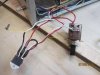
002_zpsuzlrsghd.jpg


I have the load on M1(out to transformer & switched outlet)
AC in to switch (in on position) then to M2
Snubber resistor M1 to M2
Gate to switch in off position w/resistor. 100ohm 1/2watt

plugged in via bdt, just turns on by itself no matter what position the switch is in.
 

Attachments

  • LABELED.jpg
    LABELED.jpg
    68.8 KB · Views: 64
Last edited:
There should be no path for AC or DC from M1 to M2 except the internal die. The snubber is a 100 ohm resistor in series with a .1µf safety cap. I'd have expected a straight 100 ohm resistor to smoke if used without the cap. But you've shot the turn-on mechanism via gate-to-MT2 all to hell by leaving out the cap. ;)

Cut the resistor out of the circuit. Ought to solve your problems.

And still, those wires from the power switch to the triac are 10x bigger than you need.
 
Not directly related to the triac...

Doesn't there need to be jumpers to parallel both ends of the switch in order for both pairs of contacts to be in circuit?

kwape, were there two jumpers on the back of the switch originally? I only see one jumper in your pic
 
Not directly related to the triac...

Doesn't there need to be jumpers to parallel both ends of the switch in order for both pairs of contacts to be in circuit?

kwape, were there two jumpers on the back of the switch originally? I only see one jumper in your pic

By jumpers I assume you mean the single strand connecting the two pins at the end of the switch. In that case no, just the one. lol, forgive my b/s

there were 3 leads off the switch originally. AC, switched rear outlet, and transformer.
The transformer and switched leads ran from each of the 2 front posts(in off)
The AC ran from the rear post w/jumper.

when it is switched on, I believe it is in parallel with the single jumper.


001_zpskowznnxd.jpg


See those 2 ball bearings. I suggest no one try this unless you're willing t spend an hour putting it back together. But it is clean now. and tape is your friend
 
Last edited:
Back
Top Bottom