• The move to the new server is done. There are some software and database maintenance updates in process. This has us passing the hat around to help out. We appreciate any donations. Seriously, even a dollar helps. The payment page may be found here - https://www.audiokarma.org/support.html

KR9940 in the house

rickl

I'm just a bass player
Subscriber
Picked up a KR-9940 tonight from a friend. It was sitting in his basement for many years. It is very dirty and hopefully didn't bring any bugs in the house.

It weighs nearly 50 pounds and not very easy to move around. Looks complete but the owner said he had a tech look at it many years ago but couldn't fix it after having it for 2 years.

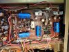
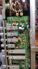
First thing I noticed was the 20 amp main fuse. I hate when I see this. A few pics. Note the KCD-2 Demodulator.
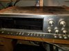
kr9940-front.jpg
kr9940-.jpg
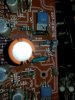
kr9940-r49.jpg

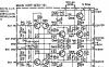
Note the burned resistor R49 on the main amp. Need to study the schematic to understand but Qe17 might be suspect. I did find glue related corrosion on one resistor.

The solder side has been worked on so this could be a long project.

kr9940-main.png

I hope to start digging into this by Sunday so stay tuned!
 
Last edited:
Register to hide this ad
spent a few minutes last night and all drivers (Q13-20) test fine. Pulled C34 and cleanup up the assembly glue. I should have tested the cap since I don't have a 220/50 in stock.

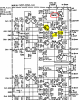
I also found two resistors open (R49,R61). Looks like I need to test Q8 on the heatsink.

main-markup.PNG

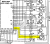
main driver board to outputs:
main2output.PNG
 
I'm going to recap/rebuild the power supplies and protection boards. then we can see where we are at. I'm not convinced the old PS caps are keeping up.

Stay tuned....

I am stuck and need help.


Using a DBT, I able to get the receiver out of protection by removing either Qe13 on the amp board (driver) or remove the connector g-06 to the outputs (see pic in above post). I currently have the protection resistors Re57/Re58 disconnected.

Qe13 or g-06 knocks the power supply voltage down and activates the protection relays. Seems like a short somewhere around Qe13/Q7. I did test Qe5 and the STV-3H diode chain. I should test Re25 but now just guessing.

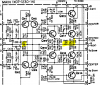
I tested the driver Qe13 and all the outputs and they test fine. Here is a pic showing the bad parts (highlighted in yellow) that I replaced. Qe9 was replaced with a KSC1845.

amp-sch-snip.PNG

Note pin 6 on the amp board titled 'base' goes to the base of output Q7. It tests fine (pulled it) but if I had a spare MJ21194G, i'd replace Q7. All my high power output spares are TO-220 style and not TO-3.

I've check most of the components on the Amp board. I have not installed many fresh caps hoping to get it working before I get it working better.

I'm open to ideas.

I've had this on the back burner while working on "easy" stuff (citation 22, KA3500, Hafler 200, C2, PAS3) but I need to get this working.
 
Last edited:
Added fresh caps to the power supply board. Voltages look good compared with schematic.

Continue to find and replace out of spec resistors but still can't get it out of protection with Qe13 installed.

1590 ps.jpg

I'm open for ideas?
 
Well, got it working.

Here is one channel.
Selection_003.png

Still needs work. Left front has high DC (90mV) and left rear has low output (2Vpp vs other channels 30Vpp).

Going to clean switches and see if that helps.
 
Last edited:
I finally got this working to my satisfaction.

Bias close to 25mV for each channel (all 4 channels) and DC offset 3mv to 35mV. good enough.

Once I got it working, I recapped the power supply, protection and amp boards. I'm sure the tone boards could use a recap but I haven't got to it yet.

Sounds good for the last 2 hours. This has been a difficult receiver to get working.

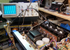
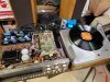
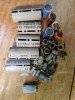
A couple pics might tell the story.

kr9044-working.jpg
kr9044-caps.jpg
 
I noticed the other day that my KA-7002 had bias that drifted. Had me puzzled for a minute until I found the clip that holds the STV-3 diode against the heat sink had relaxed. I put a slight bend in it and a dab of HS compound and remounted it. Might be work a look on your receiver.
 
thanks. one did come loose. I reapplied some heat sink compound too.
 
Last edited:
Well, Channel A blew up taking out Qe1-5. I replaced the diff inputs with a matched pair of KSA992. Found Ce17 on Qe9 open. Subb'd in a 47 puff silver mica.

Now I can't get the bias set. it sits around 2.4 Volts (not mV) across the Q8 output R16.

I've started throwing parts at it in a desperate attempt to fix the channel.

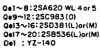
Qe13 2SC381 -> MJE15030
Qe17 2SB536 -> MJE15031
Qe9 2SC983 -> KSC1845

And outputs
Q1-8 2SC287 -> MJ21194G

new bourns multi turn pot for VRe1, all resistors tested or placed.

About the only thing I haven't replaced is STV-3H (don't really know an equivalent).

Achannel.png

upload_2019-10-18_13-41-9.png

All voltages look ok (a bit high when compared to the voltage chart).

Any ideas or other things to test?
 
Last edited:
i'm still struggling to get Channel A bias set. Still around 2.4v. I fixed a lot of cold solder joints and there might be more.

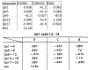
Here are the measured voltages around channel A and compared to the voltage chart.

amp-measured.png

most voltages look fine but the bases of the Qe1-5 are about 1/2 of the expected values. I need to compare to another channel but is this a problem?

Tonight I'll compare voltages with Channel B or C but if someone has an idea, please let me know.

Thanks!
 
Still have mine opened up on the bench as I compile transistor replacements, if you need me to take any measurements or more pics just let me know buddy!

P.s. As a newbie the only thing I noticed that may or may not be an issue is once those 3 metal clips were removed/installed it scratched away some of the mask exposing copper. I assume it could cause issues if knicked in the wrong spot and then the clips reinstalled, but not sure. Probably trivial to more experienced folks though.

Visible here, especially top right https://imgur.com/a/zQaDCFr
 
Finally got channel A biased. Q8 emitter resister seemed to drift once warm.

Works great until I installed the bottom.

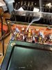
Then this
20191113_185709.jpg
 
Sounds like a wire is exposed to the bottom panel

My first thought too. I pulled the bottom panel and didn't see anything exposed. This is the same channel I've been fighting since April. I might have replaced R49 3 times. Now it won't come out of protection. All transistors, most caps and even a few resistors have been replaced on this channel (channel A for those reading along). Probably a few more might have been taken out during this smoke test.

My guess moving the amp around flexed something and caused a cold solder joint. This receiver weighs a lot and I fixed many cold solder joints on the board below the amp board pictured.

I was more impressed with getting the pic.

Time to tear into it again.
 
Last edited:
This one is probably obvious but just thought i'd throw it in since I noticed it as potential bottom cover damage upon removing mine.

That wire was pretty gouged up, a couple other nearby ones circled had knicks too. Not sure if my bot cover had even been removed since leaving the factory since most stuff looks untouched.

high res version hosted: https://imgur.com/a/YDPe4AB
 

Attachments

  • 20191115_090410.jpg
    20191115_090410.jpg
    68.3 KB · Views: 30
Thanks guy. I'll definitely look again. I was really depressed when this happened and my not have looked close enough.
 
Thanks guy. I'll definitely look again. I was really depressed when this happened and my not have looked close enough.
Definitely seems like you've been having a run of bad luck, with some patience i'm sure it will get nailed down soon.

Seems like this unit isn't too commonly worked on or spoken about online, so we definitely have a bit of a challenge in that department.

If you think it'd help and if ya got the time or desire, feel free to take high res pics in a close up grid pattern of everything and throw em up on imgur, I definitely wouldn't mind snooping through em all and seeing if I spot anything.
 
Back
Top Bottom