• The move to the new server is done. There are some software and database maintenance updates in process. This has us passing the hat around to help out. We appreciate any donations. Seriously, even a dollar helps. The payment page may be found here - https://www.audiokarma.org/support.html

L-Pad wiring

Bill Murray

Active Member
Several questions re l-pad wiring. 1. Is it really necessary to wire the amp's negative and the speakers negative to the L-pad? Wouldn't it be OK just to wire them directly to each other? 2. My speakers are 60 years old and of 16 ohm impedance. It is hard to get 16 ohm l-pads today. What if I used an 8 ohm l-pad with an 8 ohm resistor in series? Would that make it 16 ohms? 3. I have 2 tweeters but only one l-pad. What if I connected each of the tweeters positive wire to the L-pad central tap output? Would that not then work on both tweeters? (I realize this assumes both tweeters are of about the same efficiency). 4. Finally, I intend to input the l-pad from my crossover freq cap of say 8KHZ and one wire of l-pad output would then go to one tweeter positive wire while the other would go to a 12KHZ cap and then to my super-tweeter. Any problems with this??
 
Register to hide this ad
Basic L-pad wiring here:
lpad3.gif
Sorry, can't help you out on the 8/16 ohm impedance question
 
What would happen if I wired an 8 ohm L-pad to a 16 ohm tweeter?

The impedience would change from 8 ohms when full off to 16 ohms full on. This then changes the crossover point by one octave as you turn the L-pad.

But you can certainly get 16 ohm L-pads all the way up to 100 watts.
 
The practical effect to my ears is what?? Will it still increase/decrease the tweeter level? Also, 1 octave is equal to how many cps?
 
An octave is a halving or doubling of frequency so how many cps it is depends on where you start counting :)

16 - 32
32 - 64
...
16384 -32768

Jumper a 16 ohm pad in, set it where you like the sound, measure each leg and replace the pad with fixed resistors of appropriate value. If the speaker moves appreciably, do it all over again, but it gets what you want both upstream and downstream of the attenuation so everything works right (just mind the power ratings). Absent that, you will need to look harder and sim the thing with details both directions.

If you are set on cutting corners, you would need to be more specific about what particular 60 year old speakers you are talking about for people to be able to help keep everything happy and leave you passable operation.
 
The impedience would change from 8 ohms when full off to 16 ohms full on. This then changes the crossover point by one octave as you turn the L-pad.

But you can certainly get 16 ohm L-pads all the way up to 100 watts.
Power handling is not a factor. 15 watts is adequate. What I need is a 16 ohm stereo L-pad as I intend to connect 2 tweeters to it, and have them both attenuated by it. They are of approximately the same efficiency. One is a Jensen RP-103 horn, 57 years old, and the other is a Sansui T-200 horn type, probably from the 70s or 80s.
 
Fixed resistors at each driver you wish to pad is by far the best way to do this.

1- Yes it is necessary to wire as instructed.
2- Yes it is important to impedance match.
3- Do not go 2 drivers to 1 lpad
4- Yes there are problems (more than 1) with your wiring proposal.
 
An L-pad puts resistance in series with the voice coil and also in parallel with the voice coil. This is done to maintain the impedance of the load because the capacitor used at the desired cross-over point is based on its impedance. Therefore, you can't just add a resistor or two to make things work out. As you move the L-pad, the resistance to the coil increase and the resistance across the voice coil decrease, both in opposite directions (assuming you are reducing volume to the driver).

The schematic of the L-pad clearly shows this happening.

As others have pointed out, a fixed value L-pad can replace the variable one, but you would need to know how many db of reduction you would want, then google an online L-pad calculator, enter the driver's impedance and the amount of reduction you would want and the calculator will tell you what values of resistors to use.
 
Fixed resistors at each driver you wish to pad is by far the best way to do this.

1- Yes it is necessary to wire as instructed.
2- Yes it is important to impedance match.
3- Do not go 2 drivers to 1 lpad
4- Yes there are problems (more than 1) with your wiring proposal.
Thanks for your reply. Item 2---Their are L-pads which claim to be good from 4 to 16 ohms, and that they have a nominal impedance of 8 ohms but can be used from 4 to 16 without a problem. -Item 3----Stereo pads, (2 pads controlled by the same knob) would seem to allow 2 different drivers. They even have screw terminals rather than solder lugs. (Calectro S2-180 for both claims).
 
An L-pad puts resistance in series with the voice coil and also in parallel with the voice coil. This is done to maintain the impedance of the load because the capacitor used at the desired cross-over point is based on its impedance. Therefore, you can't just add a resistor or two to make things work out. As you move the L-pad, the resistance to the coil increase and the resistance across the voice coil decrease, both in opposite directions (assuming you are reducing volume to the driver).

The schematic of the L-pad clearly shows this happening.

As others have pointed out, a fixed value L-pad can replace the variable one, but you would need to know how many db of reduction you would want, then google an online L-pad calculator, enter the driver's impedance and the amount of reduction you would want and the calculator will tell you what values of resistors to use.
Ain't no way I will use fixed resistors rather than a variable pot. Under different circumstances I merely need to turn a dial. My ears, rather than all the schematics or oscilloscopes in the world, are the best judge of this. Thanks for your input.
 
Ain't no way I will use fixed resistors rather than a variable pot. Under different circumstances I merely need to turn a dial. My ears, rather than all the schematics or oscilloscopes in the world, are the best judge of this. Thanks for your input.
You don’t need a schematic or a scope to use fixed resistors.

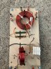
I have built about 20 crossovers with fixed resistors. My experience is that 9db of attenuation works perfectly most of the time. See the pic….the 2 green things are a 9db fixed resistor lpad for the tweeter of an hpm100. Installation is simpler and cleaner, signal degradation is minimized. There is no reason to use a variable lpad. Other than it being perceived as the easy way out. The adjustability thing is useless as they are set and forget anyways. Fixed resistors will sound better. I get how it seems harder, more complicated and done on paper rather than by ear. But that’s just what those that don’t know better think from the outside looking in.

image.jpg
 
You don’t need a schematic or a scope to use fixed resistors.

I have built about 20 crossovers with fixed resistors. My experience is that 9db of attenuation works perfectly most of the time. See the pic….the 2 green things are a 9db fixed resistor lpad for the tweeter of an hpm100. Installation is simpler and cleaner, signal degradation is minimized. There is no reason to use a variable lpad. Other than it being perceived as the easy way out. The adjustability thing is useless as they are set and forget anyways. Fixed resistors will sound better. I get how it seems harder, more complicated and done on paper rather than by ear. But that’s just what those that don’t know better think from the outside looking in.

View attachment 2591221
Thanks for your info, you have gone thru a lot of effort to reply to me. However, I do disagree with you about set and forget. I do occasionally adjust them. BTW, I just came back from a wiring experiment. It is absolutely NOT necessary to wire the negative wire into the L-pad. As long as the negative wire goes from the crossover (or the amp) to the speaker you need not send it to the L-pad. Just as in house wiring it is not necessary to have the negative wired to the switch. I have yet to determine if tapping in a second tweeter to my L-pad will have a negative effect. Prolly do that tomorrow or next.
 
Thanks for your info, you have gone thru a lot of effort to reply to me. However, I do disagree with you about set and forget. I do occasionally adjust them. BTW, I just came back from a wiring experiment. It is absolutely NOT necessary to wire the negative wire into the L-pad. As long as the negative wire goes from the crossover (or the amp) to the speaker you need not send it to the L-pad. Just as in house wiring it is not necessary to have the negative wired to the switch. I have yet to determine if tapping in a second tweeter to my L-pad will have a negative effect. Prolly do that tomorrow or next.
If I follow you correctly you are wiring the xover out neg to the voice coil neg. Then you are wiring the xover out pos to the lpad. Then out from the lpad to voice coil pos. Basically getting a variable resistor inline with speaker pos.

Is this right?
 
Last edited:
If I follow you correctly you are wiring the xover out neg to the voice coil neg. Then you are wiring the xover out pos to the lpad. Then out from the lpad to voice coil pos. Basically getting a variable resistor inline with speaker pos.

Is this right?
Yes. This is identical to the way schematics have it except for the negative wire. I did have the negative wired to the L-pad at one time, and it also worked. It needn't be there, but if it is, it won't hurt.
 
A stereo 8 Ω L-pad may be series wired to yield a mono 16 Ω L-pad.

The L-pad is nothing fancier than a voltage divider in parallel with the driver, constructed from a series resistance and a shunt resistance. The shunt diverts current away from the driver, reducing the output volume. As the resistance of the shunt alters, so must the resistance of the series be altered so as to maintain the overall resistance of the parallel path. The two values, of necessity, may be wildly different at different ends of the attenuation settings, because the overall resistance of a series-parallel circuit must be maintained at a constant value.

Draw the L-pad as a vertical voltage divider using two resistors with the output taken at the junction of the two, and this will become clear.

While the L-pad is rated as a particular resistance, that is not the nominal resistance. The L-pad is placed in parallel with a load, and thus could not be the nominal value because that would, at all times, halve the load's resistance. Instead, it has an resistance sufficient to act as a divider while maintaining the overall load resistance.

The impedance of the L-pad must, of necessity, be matched to the driver else the overall resistance of the load will change, and the corner-frequency of the filter, i.e. the crossover point, which depends upon the load's impedance, will shift.

I suggest reading any of the guides to L-pads which may be found on the web.

As an aside, the L-pad presents a constant resistance only on one side, which is perfect for crossovers since the filter is what matters. A T-pad, to contrast, has constant resistance on both sides of the attenuator, which matters in some applications, but not this one.
 
Yes. This is identical to the way schematics have it except for the negative wire. I did have the negative wired to the L-pad at one time, and it also worked. It needn't be there, but if it is, it won't hurt.
It appears that what you are doing is placing a variable resistor in series with the voice coil. You will get attenuation. So in that sense, it works. But since you have eliminated the variable resistor that goes in parallel with the voice coil, you are moving around the crossover point, altering the response of the driver AND attenuating it all at the same time while turning the knob. Ideally, you would be attenuating only.
 
It appears that what you are doing is placing a variable resistor in series with the voice coil. You will get attenuation. So in that sense, it works. But since you have eliminated the variable resistor that goes in parallel with the voice coil, you are moving around the crossover point, altering the response of the driver AND attenuating it all at the same time while turning the knob. Ideally, you would be attenuating only.
How can I be doing that? Since I have wired the crossover-l-pad-speaker precisely as the instructions say.
 
You left the negative off of the lpad. Or at least you said you did.
I have wired the L-pad both with and without the negative wired to the l-pad or wired directly to the speaker. It seemed to make no difference. The l-pad definitely attenuated without a negative connection. So I don't think it's a factor one way or the other.
 
Back
Top Bottom