
• The move to the new server is done. There are some software and database maintenance updates in process. This has us passing the hat around to help out. We appreciate any donations. Seriously, even a dollar helps. The payment page may be found here - https://www.audiokarma.org/support.html

Lafayette LR-1515 Idle Current Adjustment

Ray122

Member
Hey everyone!

Just finished recapping and cleaning up a Lafayette LR-1515 and it sounds great, but the heat sync gets really hot. Like too hot to touch. My guess is the idle current is way too high after re-capping the unit.

Usually, this isn't a big deal for me if I have the service manual, but oddly enough there doesn't seem to be too much info out there on the LR-1515, LR-2020, or similar receivers.

Anyone really familiar with these units and could tell me where to hook my meter up and what voltage or current I should set for?

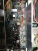
I've attached a picture of the amp board below if that helps anyone, but let me know if there are any other details I could offer to help.

Thanks in advance!
 

Attachments

  • IMG_3528.jpeg
    IMG_3528.jpeg
    126.3 KB · Views: 38
Register to hide this ad
Anyone really familiar with these units and could tell me where to hook my meter up and what voltage or current I should set for?

Not familiar to me, but if you have a signal generator and 'scope, one option might be to adjust the current, staring from the minimum setting, until you see the crossover notch disappear from the output. You can figure out which is the minimum setting by powering up the receiver via a DBT with low-wattage bulb (60W at most) and moving the adjustments for minimum glow.

Or you could check to confirm that those standup greenish parts are emitter resistors for the output stage (as I would guess), and adjust for voltage across the resistor that corresponds to oh, say, 15-20mA using Ohm's Law, voltage = resistance * current.

(I'm not sure I would rework the capacitor replacements for the sake of this, but in future work you might consider eradicating the glue that originally held the caps in place. Typical glues become corrosive over time and attack the leads of components that the glue touches. Freeze mist helps make the old glue very brittle and relatively easy to flake off.)

HTH,

chazix
 
I have the largest collection of Lafayette operating and service related manuals that still exist today. Information on the LR-1515(A), LR-2020(A), and similar type receivers are available.
 
Not familiar to me, but if you have a signal generator and 'scope, one option might be to adjust the current, staring from the minimum setting, until you see the crossover notch disappear from the output. You can figure out which is the minimum setting by powering up the receiver via a DBT with low-wattage bulb (60W at most) and moving the adjustments for minimum glow.

Or you could check to confirm that those standup greenish parts are emitter resistors for the output stage (as I would guess), and adjust for voltage across the resistor that corresponds to oh, say, 15-20mA using Ohm's Law, voltage = resistance * current.

(I'm not sure I would rework the capacitor replacements for the sake of this, but in future work you might consider eradicating the glue that originally held the caps in place. Typical glues become corrosive over time and attack the leads of components that the glue touches. Freeze mist helps make the old glue very brittle and relatively easy to flake off.)

HTH,

chazix

Thanks! Unfortunately, the CRT on my scope died over the winter. That would have worked perfectly. I really like the DBT method though, that's clever! I guess there's also no real harm in checking the voltage across those resistors as well to see what I get. This is all really good info which will definitely come in handy next time I'm in this predicament! Much appreciated!
 
I have the largest collection of Lafayette operating and service related manuals that still exist today. Information on the LR-1515(A), LR-2020(A), and similar type receivers are available.

Hey Pete, any chance you could send me a PDF or even a picture of the page that describes how to adjust the bias on the amp?
 
Hi Pete. I realize this is an old thread, but you said above that you have a huge collection of Lafayette service manuals. You mentioned the LR 1515, which I am trying to get working. Any chance I can get a copy of the schematic? Thank you. RZ
 
Back
Top Bottom