• The move to the new server is done. There are some software and database maintenance updates in process. This has us passing the hat around to help out. We appreciate any donations. Seriously, even a dollar helps. The payment page may be found here - https://www.audiokarma.org/support.html

Late model 400 Phase Inverter Adjust

Kelshar

Member
I purchased my first Tube in late May, Fisher 400. Everything seems to work but due to it's age I want to ensure it works great for another 50+ years. I have been reading the Fisher forum and want to replace all of the things that need to be replaced and keep this 400 safe, reliable and sounding better than new for years to come!

I was looking for the physical location of *C52C*. I found it on the schematic but not yet on the chassis.

I need to start a parts list and purchase the parts and slowly replace all that I can to make this Fisher 400 a life long friend.

( I am reposting this in the general forum. thanks Dave )
 

Attachments

  • Resized_20160704_182701.jpeg
    Resized_20160704_182701.jpeg
    98.4 KB · Views: 15
Register to hide this ad
Great! Now it will be easy for everybody to respond without cluttering up the sticky. As I mentioned in my response there however, C52 is a 4 section can cap. It is the UNCOVERED can cap of the two can caps that are located together at the rear TOP of the chassis. Section C (for cap C52C -- along with C52A, C52B, and C52D)) is located within this can, with connections for all four sections appearing below the chassis.

There are plenty of great folks here who have 400 receivers (including me), to help you along the way.

Good luck with it!

Dave
 
Thank you Dave. I've been reading this forum since I first received my 400 and I really like how everyone helps each other out.

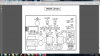
I just attached a photo and I think that I finally found it!

if I did all things correctly ( big IF ) then these are the readings that I got:
V12 - pin 1 46.80, pin 3 48.81
V12 - pin 1 46.78, pin 3 46.40
ref: the sticky on Phase Invertor Adj.
 

Attachments

  • Fisher400.jpeg
    Fisher400.jpeg
    91 KB · Views: 19
Going from the REAR of the unit, you have a cardboard covered can, This is C56, a 100uf 300v (1st section of the Voltage Doubler. It's connected to C52D via R41, a 1.2Kohm 7W green resistor (which is up between the output tubes). That's your starting point. Follow the leads from R41 back to C52D. Once at C52D, there is a 1.2KoHm 1W resistor (Band colors Brn,Red, Red, (Gold or Silver which is tolerance either 5% or 10%) connecting C52D to C52C. (Try going in clockwise direction, but Fisher sometimes went in anti-clockwise direction so watch for that.) Between C52C and C52B is R39, a 2.2KoHm (Red, Red, Red, Silver) 1Watt resistor. and between C52B and 52A is R38, a 22K (Red, Red, Orange, Silver ) 1/2watt, with R33, a 100Kohm 1/2watt to chassis ground.

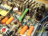
Showing R41 BTWN the output tubes.
100_3052 Modded.JPG

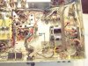
Showing C56 and C52. This particular unit has been modded with new CAN CAPS, and otheritems that aren't on your unit but the can cap location is the same. The location of C52C should be as shown but GO BY YOUR RESISTOR LAYOUT between the can cap sections. Each terminal is a section.

Larry
100_3053 modded.JPG
 
Larry, I noticed you have those "orange drops" in that unit. Are they good? I want to use good parts to upgrade mine but not sure which ones are good and which ones to stay away from. Would you be able to recommend some for me to research? thanks.
 
The P.I. readings are very close for a 1st attempt. They can be closer but for right now, it's good. The pots are fairly "sensitive" so slow, tiny, deliberate movements are mandated.


That was my 1st 400. I believe I ended up replacing the Orange drops with K-40-Y russian PIO's. It's since gone. My current 400 has 0.082uf 400v DME's in it. Really there wasn't much of any difference in the original 400 between the two sonic wise that I could tell (but my hearing is shot above 10K so it doesn't matter much what I put in). CORNELL DUBLIER makes a good film cap in the DME series which more than a few of us think is a very good replacement. The mylar's(ERO-FOL II) in it now usually don't go bad, so hang on to any that you do replace. You'll want to replace the output couplers along with the grid return resistors to be able to accomodate old and new tubes without having problems with them. But we'll get into why later.

The DME's are about 1/5th the size of an equivalent O.D. and cheaper in price too. In a receiver you have some RF(Radio Frequency) interference internally. Shielding and good lead dress address a lot of this but as far as component size, a physically smaller component for a given value is a Plus. Being smaller it won't pickup as much, if any RF interference as a physically larger component. So you have much less floor noise with no signal.

Antique Electronic Supply(AES) (www.tubesandmore.com ) has axial Illinois MPW and MPX series YELLOW caps. These are very good.

What you install on one side, do the exact same for the other side. And don't just use one brand/type everywhere as the sound can be impacted slightly by the brand/type of cap. Mix them up a little as this will minimize the brand sound (of the caps.)

There is one electrolytic cap that you WILL replace with a film cap. That is the 1uf 350V cap (C210) in the Multiplex Unit. A DME or ILL yellow 1uf-400V will work fine.

99% of the parts you will need for the 400 you can get @ Mouser including individual caps for stuffing the can's. If you'd rather go with pre-made can caps, HAYSEED HAMFEST has a 400 specific kit for the CAN CAPS. The outsides of the can's are slightly different design from the originals but it's a minor point. They are made from 105*F rated Nichicon caps and have a heavier base than the FP types.

The FP TYPES from AES are more generic and will result in having to install underside individual caps to finish it out.

You CAN find what are called "pencil type" caps in most voltages and values, so you can stuff the can's. This is the cheapest option but for a 1st time rehab probably the hardest to do.

Suggest when you get ready to start rehabbing the 400 you starta new thread and we'll go thru stuff you need to know, equipment to get to do the job without getting in too deep, and what parts to get and where. We'll suggest where, and what, but leave the looking up to you. (good practice).

And just for FYI! There are no dumb questions here, except one. And THAT question is the one that needs to be asked but doesn't get asked because you feel it's embarrassing, or paint's you as a member of the shallow end of the Gene pool. We've all BTDT so ask away. Oh sure, a few might make pointed comments, and wisecracks, but it's all in fun. I've asked my fair share and then some. So I've BTDT, got the T-Shirt, Watched the movie and read the book. (The book is better!). As long as you learn from the experience, all is good. And you'll learn a lot.

Larry
 
Larry, thank you very much for the info. Once I get my list together and start ordering parts I will begin a new thread. I am eager to learn and very much want to make this 400 reliable, safe and sounding great for another 50 years, if at all possible.

I am considering making some sort of tags to identify the individual components so (1) I know where and what they are (2) obvious reasons for replacing, repair.

p.s. great forum and people here!
 
Hello Larry, I have searched the schematic from top to bottom and can't seem to find (C210). I don't see anything above c100. IF I was reading it correctly it says Last is C100 and R138. I'm still learning to read these so this will help once I can figure out where things are. thanks.
 
C210 is on the MPX schematic. If your's has never been touched, it'll be a 1uf 350V axial FRAKO brand, sitting on the chassis with a lead to the one side of the MPX box, and the other to the COIL in the MPX. IT's Polarized, but putting a 1uf 400V film in it won't matter. Either way is fine.

Pic shows a 1uf 400V Cornell Dublier DME series Film cap in place of the electrolytic. It's a bit tight to get to so cut the leads off as close to the body of the E-Cap as you can and "J" HOOK the wires, crimp together and solder.

100_4785 modded.jpg
 
To answer your question about what caps to use, you can basically use any brand/type you can physically fit in it as long as the value and voltage are the same or slightly higher. For example. You'll see .02 caps and .4.0uf caps. Back about 1970 there was an industry wide value change (someone had to justify his job) so that almost no multiples of 5 or 10 were left. what you ended up with were stuff like .022, and 4.7 or variations on a theme. Plus caps back then had a value tolerance of up to +90% and -50%. Meaning a cap that was 4uf could be as low as 2 uf and as high as 7.5uf and still be in spec. Now the highest tolerance is also the general standard of 20% Plus and minus. There are obviously 5% and 10% and the ocassional 1%. If you are doing a total component replacement of the underside (over 50% of the parts including resistors, caps, coils, trimmers, etc, then a tighter tolerance would help if you wanted to spend the $$. Even doing one circuit (for example the phono preamp) in 5% or 10% will help with keeping the RIAA curve in check. Tightening up the Tone circuit PEC's (Packaged Electronic Circuit) by using 1% or 5% replacement parts helps a good deal. But generally using a 20% part will do that over the original part.

Back to what to use. Package wise, smaller the better in most cases as this is a receiver and the larger the casing, the more chances are that it will act as an antenna and introduce RF interference into the circuit. Then you're chasing noise that you have a hard time finding out where it's coming from until you remember that certain caps near power supply and rf circuit path's will act as antenna's. Going from a physically large to a physically small component (keeping the value and voltage the same) will in most all cases get rid of the noise. Which is why I don't like sprague ATOMS's in a receiver. Comparing a DME to a ATOM is like comparing a 1958 Renault Dauphine to a New 18 wheeler Tractor-Trailer combo. Size does Matter in this case.

Installing all one brand/type of cap in a unit can impart a flavoring of that cap. Some are overly bright (what I call shrill) or overly Dark (what I would call dull or blah). You can mix them up some BUT! What you put in the RIGHT CHANNEL, do the exact same for the LEFT CHANNEL.

Take a look at these two pics. SAME UNIT. Before Rehab and about 95% done on the 2nd. Note the different caps in the main areas.

Illinois MKP Axials (Yellow) in the Tone area.
DME and Orange Drops in the Phono Section
DME's in the output section and Power supply
Nichicon UHE's or UPW in the POWER SUPPLY E-Lytics.
Nichicon UKL in the other Non Power supply E-Lytic caps.

Some guys get quite fancy with what i term "Boutique" caps (fancy Paper in Oils, Foil in water, etc, etc, etc. at exorbitant prices(at least to me)). On ocassion I may use K40-Y, K-42-Y, or K-73 films in real tight areas provided I can get them very cheap. Jack Benny takes a back seat in that 29 Maxwell of his to me, according to my wife.

It all boils down to personal preference, and the fact that caps on the the worst end of the spectrum today, are generally better than the best caps of 1950-60-70. Orange drops are good caps. And this B.S. about the 715's are better than the 716's you can't tell by my ears. They sound exactly the same.

Speaker cables. FISHER Recommended basic 18ga zip wire up to 50 ft away. From 51 to 100ft it was 16ga. If all I need it 6 to 12 ft, I go down to Home Depot and buy a couple of the inexpensive extension cords in brown or black, and cut the ends off. Works fine.

Interconnects (RCA Cables). The Inexpensive RCA Brand or even the PARTS-EXPRESS brand in 6ft and 3ft are fine. The ends are slightly large for the center to center width between the jacks but trim off some of the molding and they work fine. No need for monster cables.

Larry

BEFORE. This is as I got it. Some work had been done prior to my getting it. It all got ripped out and redone.
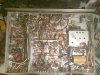
400 inside overall.jpg

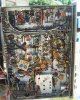
AFTER; The little board sitting cock-eyed is the Individual Balance-Bias Adjustment (IBBA) Board. I did change the location of the BIG 1.2K 7W resistor from between the output tubes to under the can caps. Makes more sense there to me and it doesn't interfere with the screen stability resistor layout. It's now a 10W resistor. The 330ohm 3 watt resistors on the 3 section cap were also changed to a 5w resistor. There are some wiring changes that affect the Tape Monitor / Aux sections, but that should be covered later AFTER you do the basic restore.

Your list looks good. Get about 10 rubber grommets to redo the ones on the phono tube sockets. The part # from mouser is in the COMMON PARTS NEEDED FOR FISHERS Sticky thread at the top of the forum. Also the rectifier is listed. The 2 diodes on the 1st cap can be 1n4007's but I'm a little leery of them at this spot, so I use 1n5406 or 5408. These are 3Amp diodes vs 1Amp diodes for the 1n4007's. Also add a CL-80 (just 1) to the power lead from the wall. In the pic it's just above and to the left of the bias caps. You may have to lighten up the pic to see it clearly.

400 inside After.jpg
 
Last edited:
from this chassis layout, I can then determine these areas?

Illinois MKP Axials (Yellow) in the Tone area.
DME and Orange Drops in the Phono Section
DME's in the output section and Power supply
Nichicon UHE's or UPW in the POWER SUPPLY E-Lytics.
Nichicon UKL in the other Non Power supply E-Lytic caps.
 
Lee; I've got Rogerfederer's 400 on the bench now. I'm gonna follow your restoration for this one along with some of Dave's special sauces. Should be kick-ass. And then add some of them to mine when I get done with roger's.
 
Lee, thanks very much for sending and spending your time to label the individual components! This will help tremendously. Now I need to get some part numbers and place an order with Mouser.
I found a place to use up a gift card!!!!

me too Larry
 
Back
Top Bottom