You are using an out of date browser. It may not display this or other websites correctly.
You should upgrade or use an alternative browser.
You should upgrade or use an alternative browser.
Leak Stereo 20 transformer overheating
- Thread starter bdbell
- Start date

bdbell
Active Member
Thanks again everyone...finally getting back to this. I am going to replace the filter caps - have some Nichicon 500v CY series.
When looking into it I had seen several builds where people have added a fuse after the 100ohm, found the following mod somewhere...

I did add a fuse, but obviously that did not blow when the 1 watt resistors got too hot and disconnected so not very effective! I did not install the diodes noted there.
It's going to an elderly gentleman that wants to be able to use it without worrying it's going to go nuclear - so I would like to do everything possible to make it safe...any suggestions on how to better implement a fuse - or is the 315mA just too high a value?
When looking into it I had seen several builds where people have added a fuse after the 100ohm, found the following mod somewhere...
I did add a fuse, but obviously that did not blow when the 1 watt resistors got too hot and disconnected so not very effective! I did not install the diodes noted there.
It's going to an elderly gentleman that wants to be able to use it without worrying it's going to go nuclear - so I would like to do everything possible to make it safe...any suggestions on how to better implement a fuse - or is the 315mA just too high a value?
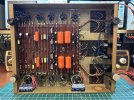
Attachments
bdbell
Active Member
I have been testing this amp - there is also a Point One and Varislope preamp - when I first tested the Point One with the amp, I saw the current rise that signals it is starting to go out of control...so I tightened and cleaned the sockets in the Point One - they are different than the amp and varislope and the poorest quality. I did at least two tests with the Point One after that and another with the Varislope - each one for 2+ hours where the current draw sat at 0.91/0.92 for the duration - and the voltage between the amp/preamp was almost exactly where it should be - 195v.
Yesterday morning I tested the Point One, saw a current rise, so decided to change the tube sockets in it. I found at least two that had one half of the two pieces that grip the pins broken so obviously they needed to be changed. I also re-tightened all of the pins in the amp and ran another test this morning...and within 20 minutes the current draw was nearing 1.15 amps and the voltage between the two was rapidly dropping - at 180v when I shut down. New sockets, tightened sockets, almost all new caps and resistors - pretty sure if I try it again it's going to be a 50/50 weather it works or goes nuclear...what else could be cause the amp to sometimes suddenly start to require more current and increase to the point where it overheats or blows something...the transformer was not even warm...
I know tubes are a possibility - but all the tests have been done with the same tubes, would a bad tube not always cause a problem?
Yesterday morning I tested the Point One, saw a current rise, so decided to change the tube sockets in it. I found at least two that had one half of the two pieces that grip the pins broken so obviously they needed to be changed. I also re-tightened all of the pins in the amp and ran another test this morning...and within 20 minutes the current draw was nearing 1.15 amps and the voltage between the two was rapidly dropping - at 180v when I shut down. New sockets, tightened sockets, almost all new caps and resistors - pretty sure if I try it again it's going to be a 50/50 weather it works or goes nuclear...what else could be cause the amp to sometimes suddenly start to require more current and increase to the point where it overheats or blows something...the transformer was not even warm...
I know tubes are a possibility - but all the tests have been done with the same tubes, would a bad tube not always cause a problem?

it only starts to run away with the preamp hooked up? Wouldn't expect that could draw enough to matter, or cause this. Can you unhook the audio inputs from the preamp and just leave the power leads connected to see if that changes anything?
Do you have a scope? I'm sort of wondering if its oscillating for some reason. Thats about the only thing that comes to mind that could cause it to eat a lot of current, but somewhat inconsistently. If whatever was going on only got triggered under specific conditions it might behave or not at any given time. If it is oscillating, I'd expect that pulling either the EF95 or ECC83 would stop it.
Do you have a scope? I'm sort of wondering if its oscillating for some reason. Thats about the only thing that comes to mind that could cause it to eat a lot of current, but somewhat inconsistently. If whatever was going on only got triggered under specific conditions it might behave or not at any given time. If it is oscillating, I'd expect that pulling either the EF95 or ECC83 would stop it.

Correct with the 3-watt resistor. I suppose a good 100-ohm, 2-watt may work, as long as you fix the instability issue.Thanks everyone for the replies! I had run the amp last night without tubes for quite a while - almost no current draw and barely got warm after ~90 minutes, and voltages were all stable. I also have already replaced the 100ohm with a proper single 3 watt - and I went through and replaced any out of tolerance resistors. I do have a 5 watt resistor, but I was under the impression that the 3 watt was part of the safety mechanism with this as was the client so they wanted to keep it at 3 watts - is that not correct?

If you are seeing excessive current draw over time (and all tubes are in), it could be due to unstable parasitic oscillations. Do you have access to test equipment, such as a signal generator and a scope?
Last edited:
the EF95
derp, these don't run a pentode input. For some reason I was thinking it did. 1/2 ECC83 voltage amp. Whatever.
anyway these have grid stoppers where it makes sense. 22k at the grid of the first tube, 10k into the output tubes. One thing they don't have is an HF limiting network off the plate of the voltage amp though so it may be somewhat prone to having response further out than really makes sense. No idea what the stability is really like on these, not all old designs were completely rock solid though.
Last edited:
bdbell
Active Member
OK, well I have done some more testing...it does seem to occur when the preamp is connected more often anyway so I have been leaving it connected during the tests, as I mentioned it's going to an elderly gentleman and I would like to make it as reliable as possible.
I watched the video and connected things up with scope/sig gen - with no signal I was not seeing any oscillations initially, and no differences with treble/bass adjustments - but I figured out where the current draw is coming from - one tube is red-plating. The cathode bypass resistor is discolored. I just replicated it and saw the tube start to red-plate. The tube tests fine - (it's a quad of Sovtek EL84/6BQ5) same tube has run for 4 hours several times - so is it the socket? All the resistors have been replaced - grid resistors are Dale CMF 10k 1% 0.6 watt.
BTW - this is the same location that had a burnt cathode resistor when I got the amp.
this is what I see shortly after turning on? no input, volume at zero. after a while this went away and it was a flat signal
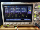
but every once in a while it does this - still zero volume;
when the tube was red-platting this is what I saw just before turning off
I know I should swap tubes to see if it follows the tube, need to run out for a bit but will check the replies before I test when I get back.
I watched the video and connected things up with scope/sig gen - with no signal I was not seeing any oscillations initially, and no differences with treble/bass adjustments - but I figured out where the current draw is coming from - one tube is red-plating. The cathode bypass resistor is discolored. I just replicated it and saw the tube start to red-plate. The tube tests fine - (it's a quad of Sovtek EL84/6BQ5) same tube has run for 4 hours several times - so is it the socket? All the resistors have been replaced - grid resistors are Dale CMF 10k 1% 0.6 watt.
BTW - this is the same location that had a burnt cathode resistor when I got the amp.
this is what I see shortly after turning on? no input, volume at zero. after a while this went away and it was a flat signal
but every once in a while it does this - still zero volume;
when the tube was red-platting this is what I saw just before turning off
I know I should swap tubes to see if it follows the tube, need to run out for a bit but will check the replies before I test when I get back.
bdbell
Active Member
Thanks again @gadget73 - coupling caps have been replaced, old stock - but good 600v orange drops (there is a pic earlier in the thread). I checked for DC on the grids though - seeing almost 2v on the grid of the tube that red-plated, switched it to another socket and the leakage followed the tube - have replaced that tube now and no DC on the grids.No chance its a leaky coupling cap or high resistance grid to ground resistor?
would say that's probably it - but after all the problems with this one I am going to do more testing yet and will update.
bdbell
Active Member
I ran the amp and preamps for hours yesterday - voltage out of the rectifier varied only a few volts - 330-338, averaging around 334v - current draw was just under 0.9amps and after almost 9 hours running the transformer was at 50C...not that hot for a transformer - pretty sure all is OK now.
Only thing really still want to deal with is fuse. I took the one I had put in after the 100ohm and was about to put it before the rectifier, when I realized I needed the higher voltage fuse and I don't have anything, and can't get anything local. Before I order something, I wanted to ask if just reducing the external 2 amp would be a possibility. It averages at 0.9amp, and I know that if the amp draws over 1 amp there is something wrong, I know that a 1amp fuse is too small, but 1.25 or 1.5...I know it's a lot more complex that that as I saw in the conversation where I originally read about adding the fuse, but as always any feedback is appreciated!
Only thing really still want to deal with is fuse. I took the one I had put in after the 100ohm and was about to put it before the rectifier, when I realized I needed the higher voltage fuse and I don't have anything, and can't get anything local. Before I order something, I wanted to ask if just reducing the external 2 amp would be a possibility. It averages at 0.9amp, and I know that if the amp draws over 1 amp there is something wrong, I know that a 1amp fuse is too small, but 1.25 or 1.5...I know it's a lot more complex that that as I saw in the conversation where I originally read about adding the fuse, but as always any feedback is appreciated!
You can use a 125 or 250 VAC fuse, as long as the current rating meets OEM specs.When I realized I needed the higher voltage fuse and I don't have anything, and can't get anything local.

Last edited:

Lavane
Lunatic Member
So that tube isn't red plating now?
I've had two 6P14P-P's red plate right out of the box. The Sovtek EL84M's are just supposed to be 6P14P-EV's. Maybe the Sovtek EL84's are
6P14P-P's? The P's being the shorter lived 3000 hour version.
Anyway, both of those tubes tested strong like new. It didn't matter if I plugged them into my PP console amp, or a single ended amp I have, they redplated.
I've had two 6P14P-P's red plate right out of the box. The Sovtek EL84M's are just supposed to be 6P14P-EV's. Maybe the Sovtek EL84's are
6P14P-P's? The P's being the shorter lived 3000 hour version.
Anyway, both of those tubes tested strong like new. It didn't matter if I plugged them into my PP console amp, or a single ended amp I have, they redplated.
Yes, plain Sovtek EL84 are Saratov, Reflector-made, General Purpose use (not mil-spec) 6P14P.Maybe the Sovtek EL84's are 6P14P-P's?
Anyway, both of those tubes tested strong like new. It didn't matter if I plugged them into my PP console amp, or a single ended amp I have, they redplated.
Lavane
Lunatic Member
I kind of figured that. I'm using Sovtek EL84M's in my ST-35.Yes, plain Sovtek EL84 are Saratov, Reflector-made, General Purpose use (not mil-spec) 6P14P.
Those 6P14P-P's I'm using in the magnavox 9303, and DG1 amp sound really good too.
bdbell
Active Member
I replaced the tube that was red-plating. These just have EL84/6BQ5 marked on them - so are the M version?
I did have a CL80 installed, but I moved it to before the fuse now and am going with a 1 amp fuse - I know from several days of testing that if the amp is drawing that much it's in trouble. If the 1 amp is blowing we will up it to 1.25 but a half a dozen tests so far and it's been good.
The client wants to put a quad of 7189 in it - from everything I have read that should be fine but if not let me know.
I did have a CL80 installed, but I moved it to before the fuse now and am going with a 1 amp fuse - I know from several days of testing that if the amp is drawing that much it's in trouble. If the 1 amp is blowing we will up it to 1.25 but a half a dozen tests so far and it's been good.
The client wants to put a quad of 7189 in it - from everything I have read that should be fine but if not let me know.
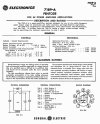
7189 is just a 6bq5 rated to handle more voltage. They are completely backwards compatible. The 7189A may not be though. Same tube, but on a 7189A pin 1 and pin 2 is G1. 7189A also has G2 on both pin 6 and 9. 7189 and 6bq5/EL84 have pin 1 and pin 6 marked as IC.
basically make sure nothing is on pin 1 and pin 6 of the output tube sockets and it'll be perfectly happy with any 6bq5, 7189, or 7189A you want to pop in there. Once in a while those get used as tie points for things that can't be tied to G1 or G2.
basically make sure nothing is on pin 1 and pin 6 of the output tube sockets and it'll be perfectly happy with any 6bq5, 7189, or 7189A you want to pop in there. Once in a while those get used as tie points for things that can't be tied to G1 or G2.
With the real 7189A, in case you wondered why pins #1 and #2 are on G1 and #6 and #9 are on G2 — I was told by a tech a long time ago, GE designed that to help increase heat dissipation from those grids. Those extra pins act like a heat sink.But on a 7189A pin 1 and pin 2 is G1. 7189A also has G2 on both pin 6 and 9. 7189 and 6bq5/EL84 have pin 1 and pin 6 marked as IC.