

You are using an out of date browser. It may not display this or other websites correctly.
You should upgrade or use an alternative browser.
You should upgrade or use an alternative browser.
Leak Stereo 20 transformer overheating
- Thread starter bdbell
- Start date

miles2go
Active Member
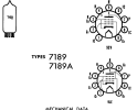
That is interesting info... Not only the max screen rating (400v), but the plate max of 440v with a 13.2w max dissipation rating makes me think that with the 7189A, there is more than meets the eye, considering the plate structure looks the same as the 6bq6 & 7189 varieties.With the real 7189A, in case you wondered why pins #1 and #2 are on G1 and #6 and #9 are on G2 — I was told by a tech a long time ago, GE designed that to help increase heat dissipation from those grids. Those extra pins act like a heat sink.
View attachment 3640310

I've heard it claimed that there is no actual difference, they just pushed the voltage ratings up to the real limits.
The plate dissipation is a rating system change. The 6bq5 is design center, the 7189 and 7189A is design max which is 10% over design center, or 13.2 watts. Somewhere there is a 7189 datasheet with a 12 watt design center rating but most of them are design max.
The plate dissipation is a rating system change. The 6bq5 is design center, the 7189 and 7189A is design max which is 10% over design center, or 13.2 watts. Somewhere there is a 7189 datasheet with a 12 watt design center rating but most of them are design max.
miles2go
Active Member
Yea it looks like the only stated difference after looking at GE tube data is the greater screen max. This is quoted right from the Description And Rating on pg.1I've heard it claimed that there is no actual difference, they just pushed the voltage ratings up to the real limits.
The plate dissipation is a rating system change. The 6bq5 is design center, the 7189 and 7189A is design max which is 10% over design center, or 13.2 watts. Somewhere there is a 7189 datasheet with a 12 watt design center rating but most of them are design max.
"The 7189-A is a power output power-amplifier pentode designed for use in the audio~frequency power output stage of television and radio receivers and high-fidelity amplifiers. The 7189-A is unilaterally interchangeable, both electrically and mechanically. It differs from the 7189 in having a higher screen-voltage rating and in specifying the internal connections to pins 1 and 6."

In my experience, the sound from a GE 7189A differs from that of a 6BQ5 of that era. The 7189A has more headroom. It doesn't compress as much under load, as the 6BQ5 — at least to my ears. More of a 6L6 like sound.I've heard it claimed that there is no actual difference, they just pushed the voltage ratings up to the real limits.
The plate dissipation is a rating system change. The 6bq5 is design center, the 7189 and 7189A is design max which is 10% over design center, or 13.2 watts. Somewhere there is a 7189 datasheet with a 12 watt design center rating but most of them are design max.
I wish I had bought more when they were still available at a reasonable price.

Last edited:
miles2go
Active Member
I have an old Magnatone from the early 60's that uses the 7189A in a push-pull. I guess it was marketed as a bass amp, but sounds sweet for guitar...
I haven't looked at the prices of these lately, but 10 - 12 yrs ago I managed to cobble a couple pairs together as replacements for that amp...
I wish I had bought more when they were still available at a reasonable price.
I haven't looked at the prices of these lately, but 10 - 12 yrs ago I managed to cobble a couple pairs together as replacements for that amp...
Lucky you!I have an old Magnatone from the early 60's that uses the 7189A in a push-pull. I guess it was marketed as a bass amp, but sounds sweet for guitar...
I haven't looked at the prices of these lately, but 10 - 12 yrs ago I managed to cobble a couple pairs together as replacements for that amp...

A good set makes a difference in those 1960s Hi-Fi and guitar amps that can use them.


Sounds as though you found your issue with one of the tubes, but I was wondering something I couldn't see from the photo or diagram. Is there a fuse prior to the transformer and does this topology utilize a thermistor or any sort to control the current inrush? The amp I just built does for the purpose of giving the caps time to charge and allowing the transformer to magnetize its core which relieves stress on components and your rectifier tube. It's an NTC thermistor which acts as a 16ohm resistor for a few seconds before it heats up, then drops to 1 ohm.Thanks again everyone...finally getting back to this. I am going to replace the filter caps - have some Nichicon 500v CY series.
When looking into it I had seen several builds where people have added a fuse after the 100ohm, found the following mod somewhere...
View attachment 3635075
I did add a fuse, but obviously that did not blow when the 1 watt resistors got too hot and disconnected so not very effective! I did not install the diodes noted there.
It's going to an elderly gentleman that wants to be able to use it without worrying it's going to go nuclear - so I would like to do everything possible to make it safe...any suggestions on how to better implement a fuse - or is the 315mA just too high a value?

The Stereo 20 has a tube rectifier which eliminates the intrush current issue.
I'm just talking datasheet electrical compatibility stuff to make sure the magic smoke doesn't come out. Whether the sonics are favorable is a lot harder to define. Swapping between different brands or variations of the same type you'll get sonic differences.In my experience, the sound from a GE 7189A differs from that of a 6BQ5 of that era.
Yeah, and I'm just saying that there is a sonic difference (not just specs).I'm just talking datasheet electrical compatibility stuff to make sure the magic smoke doesn't come out. Whether the sonics are favorable is a lot harder to define. Swapping between different brands or variations of the same type you'll get sonic differences.
And yes, the transformers should be heavier-duty (that is, the unit should be designed for 7189A use.
Referencing your post #30: I had exactly the same issue in a recently rebuilt TL50. The transformer ran hot, very hot after several hours of running, even though it tested fine after the original rebuld. Turns out that the valves used on the final version, a pair of worn out date matched GEC KT88s had indeed both gone slightly gassy. Not terrible, but enough to bring the grid voltage up to 3 volts and with the cathode bias voltage creeping up to 55 volts after 20 minutes and rising steadily to 60 volts after about an hour of soak testing at idle, which at that point was pulling around 100ma. Time to turn off and assess. As an experiment, I increased the value of the cathode resistor from the specified 600 to 700 ohms to bring the current down, but it didn't really do much to contain the voltage rise. Fundamentally once this valve pair had reached a critical threshold of gassiness, the remains of the diminished getters were no longer enough and they were both starting to go into thermal runaway. Upon replacing with known good GEC valves, the grid voltage reduced to just about zero, with the bias voltage down to where it should be at around 50 volts and current at around 80mA, and the transformer now running warm as opposed to piping hot after several more hours of running.Thanks again @gadget73 - coupling caps have been replaced, old stock - but good 600v orange drops (there is a pic earlier in the thread). I checked for DC on the grids though - seeing almost 2v on the grid of the tube that red-plated, switched it to another socket and the leakage followed the tube - have replaced that tube now and no DC on the grids.
would say that's probably it - but after all the problems with this one I am going to do more testing yet and will update.