What great info, Thanks so much. Do you guys do Carver gear? Different animal I know, But you sure know electronics.



google Chrome,Does anyone have a .pdf or another way to view this thread? Really need the pictures but the new photobucket change makes it seemingly impossible.

Hey @Leestereo I am working on an AU-7500, and it doesn't have C825,C826 on the underside of the board at all, as well as not having the C829,C830 caps at all. Should I follow what you did using the 1uf caps at C825, 826, 827 and 828 and install 47uf caps as you did on C829,C830?On the underside of the chassis, although not in the schematic nor the parts list, local decoupling capacitors (3.3µF/50V) were present for the +ve rail (the right channel capacitor is designated C828; the left channel C827 capacitor is not shown). Similarly, 3.3µF/50V capacitors were present across the bias transistors (TR807, TR808) on the underside of the F-2034 driver board (designated as C825, C826). The use of 3.3µF capacitors across the bias transistor is unusual since Sansui typically specifies a 1µF capacitor for this position in their designs. This anomaly, together with the absence of the -ve rail decoupling capacitors in this unit (which are present in the other models in the AU-x500 series) suggests that the installation of the 3.3µF capacitors across the bias transistors was a production line error. To correct this error, 1µF low ESR capacitors were installed across the bias transistors and the local decoupling capacitors were installed for the -ve rail (C829, C830). The replacement decoupling capacitors were low ESR types rated at 47µF/50V.

Thanks Lee, got that all done@JoshHendi: Yes, I do recommend adding the decoupling capacitors; that would be four 47µF capacitors at C827-C830 and two 1µF capacitors at C825 &C826 (film capacitors can be used here).
Yes, the 5.6kohm resistors were removed; during testing it was observed that the main capacitors discharged sufficiently fast without the resistors....looks like you removed R005 and R006 (56K) resistors from beneath the two large filter caps when replacing the .22uf caps?


Clean the switches and controls, preferably with the correct (two) kinds of DeOxit - in the correct order.Let me know if there is something really important that I have missed.
Thanks again for this great thread. I've been noticing a bit of hiss and general noise on my untouched AU-7500 that I've been using daily for 4-5 years now.
...but no dice on the 2700uf 80v. (Unless "snap in" can be made to work?)

Answer:@Leestereo
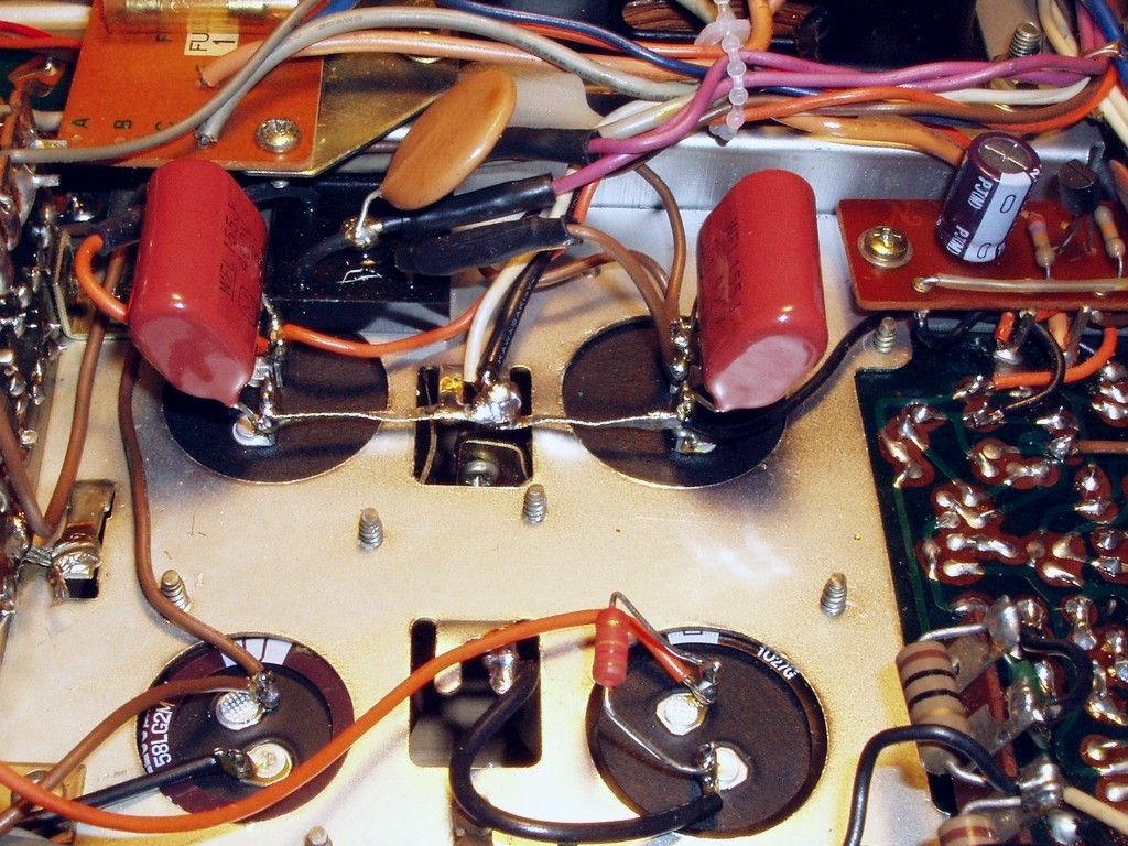
Thanks again for this amazing guide. I am in the process of replacing the large filter caps and have a question. For the C004 and C005, the 15,000µF/63V caps, I do not see the stock 5.6K resistor that bridged the terminals in your before picture. Did you simply replace this with a smaller resistor that is not visible in the photo? Or did you remove it from the circuit?
Yes, the 5.6kohm resistors were removed; during testing it was observed that the main capacitors discharged sufficiently fast without the resistors.

Part 4: Equalizer Block (F-2028)
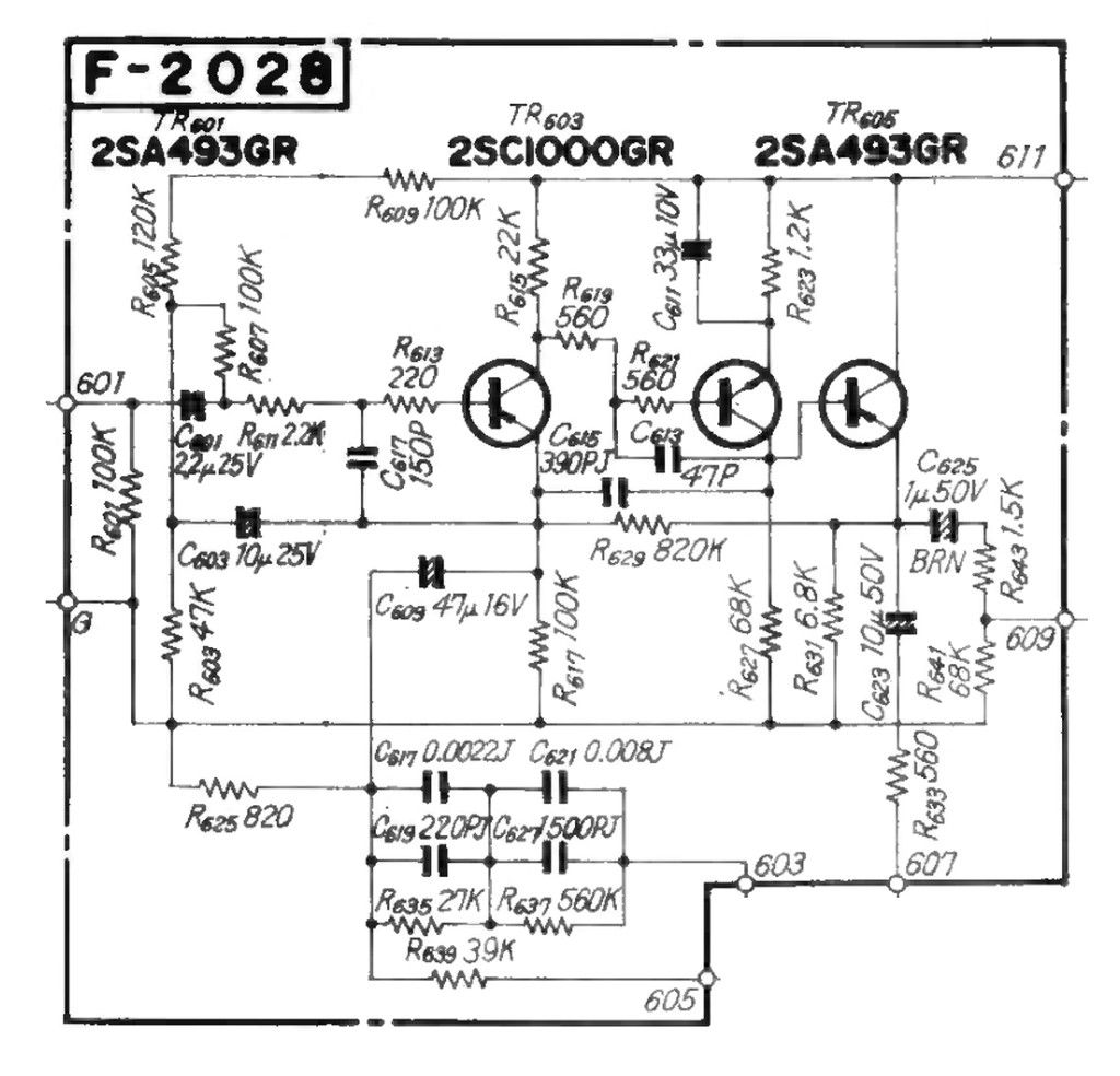
Signal Path:
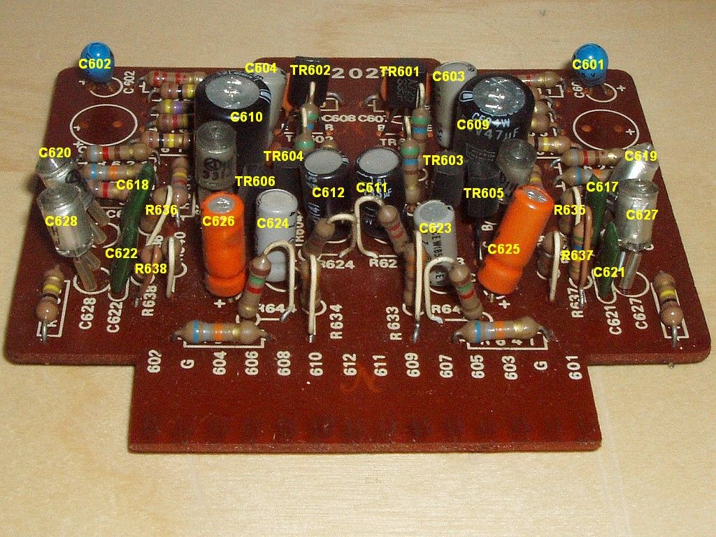
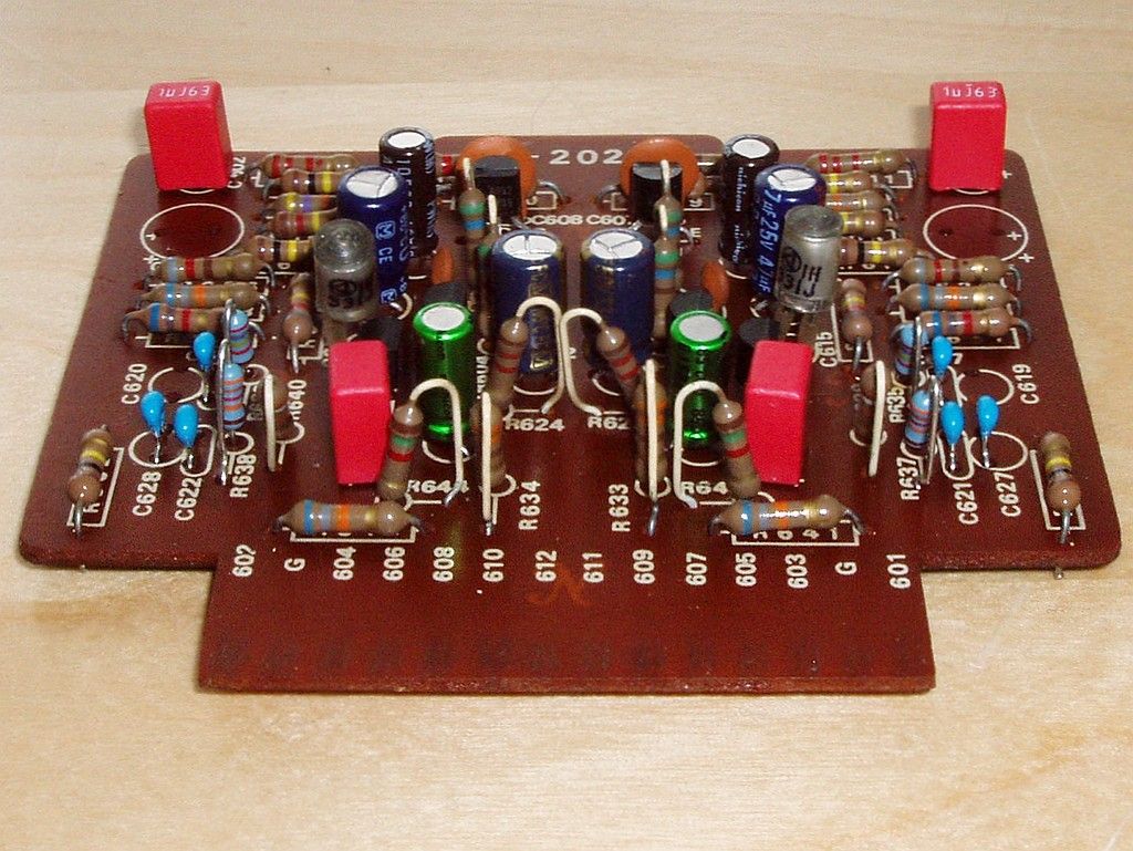
The stock capacitors (C601, C602) in the input high-pass filter for the phono input were 2.2µF tantalum electrolytic capacitors; these were replaced with 1.0µF WIMA film types (note that the F3 with the film capacitor is <1.8Hz). The capacitors (C623/C624) which feed the RIAA feedback were 1µF/50V polarized electrolytic types (rather than 10µF/50V as shown in the schematic) and the replacements were 4.7µF/25V bipolar types. The stock output capacitors (C625, C626) were originally 1.0µF/50V "low leakage" electrolytic types and the replacements were 2.2µF/50V stacked (polyester) film types.
The transistors at TR601/TR602 and TR605/TR606 were the failure-prone 2SA726 transistors (rather than the 2SA493 shown in the schematic); the replacements were KSA992 transistors. The transistors at TR605/TR606 were 2SC1313 types (rather than the 2SA493 shown in the schematic), and were replaced with KSC1815 types. Note that the pin-order for 2SA726 and 2SC1313 is "BCE" whereas the pin-order for KSA992/KSC1815 is the current "ECB" standard.
Non-signal Path Capacitors
The local DC filtering capacitors (C603/C604) were 10µF/25V capacitors and the replacements were low ESR types of the same capacity. The stock emitter-bypass capacitors (C611, C612) were rated at 33µF/10V; the replacements were 33µF/50V low ESR types.
RIAA Feedback
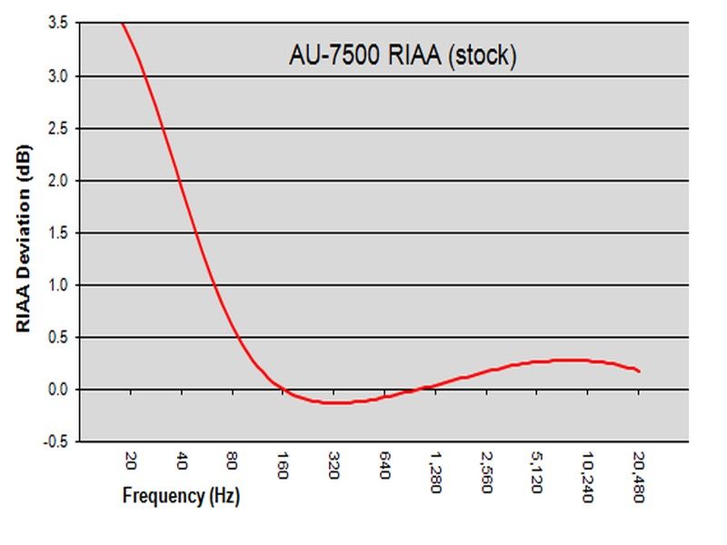
The stock AU-7500 phono stage has a RIAA equalization error that is similar to that previously noted for the AU-9500 (see Sansui AU-9500: Phono Stage RIAA Equalization Error for details). As can be seen in the graph below, there is a rising bass response beginning at ~160Hz which reaches +3.3dB at 20Hz. This deviation was corrected by replacing the 560kohm resistors at R637/R638 with 332kohm 1% metal film resistors. This single change will improve the RIAA equalization dramatically; the corrected response fits within a 0.25dB window.
The performance of the phono stage was further enhanced by upgrading all of the components in the RIAA feedback circuit with higher quality counterparts (note that replacement resistor and capacitor values were adjusted to optimize the RIAA equalization). The stock 27kohm carbon film resistors at R635/R636 were replaced with 27.4kohm 1% metal film types. The polyester film RIAA capacitors were upgraded to C0G types. For the C617/C618 + C619/C620 combination (2670pF), a single 2700pF C0G capacitor was used. For the C621/C622 + C627/C628 combination (9700pF), 6800pF + 2700pF C0G capacitors were installed. The capacitors C609/C610, which set the low end cut-off of the RIAA equalization, were 47µF polarized capacitors; the replacements were 47µF bi-polar types.
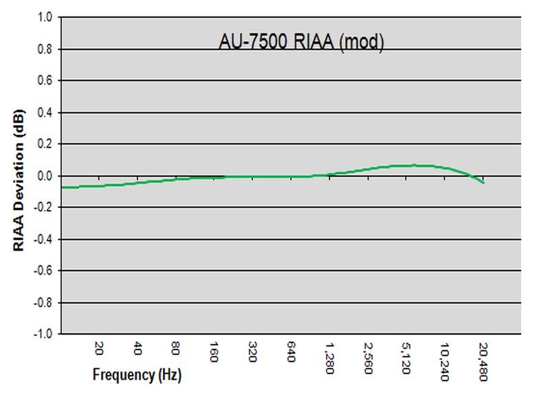
As can be seen in the graph above, the fully modified AU-7500 phono stage has a RIAA equalization curve that is very "flat"; it is ±0.1dB from 20Hz-20kHz.
Note that such RIAA equalization errors are not limited to Sansui phono stages, but rather are all too common in vintage phono stages designed prior to the late 1970s. The landmark Lipshitz RIAA paper, published in the June 1979 issue of the Journal of the Audio Engineering Society, pointed out that "Most current disc preamplifiers have audibly inaccurate RIAA equalization. These errors are due in part to the perpetuation in print of incorrect formulae for the design of the RIAA equalization networks..."