• The move to the new server is done. There are some software and database maintenance updates in process. This has us passing the hat around to help out. We appreciate any donations. Seriously, even a dollar helps. The payment page may be found here - https://www.audiokarma.org/support.html

Line stage preamp filament voltage question

kentuckycat

Active Member
I’m looking for an expert opinion on a few questions that I have regarding filament voltage. I’d like to build a preamp this winter and after reviewing schematics for the last several months I’ve decided on the JE Labs 76/6SN7 preamp. I’d like to use 12SN7’s instead, though, for a couple of reasons; 1) they’re a fraction of the cost of 6SN7's and 2) I’d like to add a 12v motorized remote volume control.

The schematic calls for raising the 6.3v filament voltage, which I plan to do. Here are my questions:
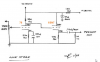
upload_2022-12-1_12-44-21.jpeg
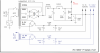
a.) If I add a separate 12v transformer, should I just duplicate the same resistors and capacitor and tie in the high voltage for the 12v filaments that I would use with the 6v for the 76 tubes? (assuming that I’d still be using the 6.3v taps from the mains for the 76 tubes) I drew this up in blue in the attached. Apologies for the neatness, I work better with AutoCAD than I do with a pencil.
upload_2022-12-1_12-41-50.png
b.) Should I instead use a separate 12v transformer with the voltage raised for all the tubes but use a voltage divider before the 76 tube filaments?

c.) Out of the many *SN7 build photos that I’ve looked at, almost all of them use half of the twin triode and abandon the other half. Why is that?

d.) I noticed from photos that most builds wire both channels to the left side of each tube. Wouldn’t it make more sense to wire pins 1,2,3 on he right channel and pins 4,5,6 on the left so that you can swap the tubes left to right at any time and basically have fresh tubes?
thanks!
 
Register to hide this ad
elevating it is a good idea. I'm assuming its for a cathode follower? That tends to have high H-K voltage if not elevated.

May also be worth seeing if you can find a transformer with a second 6.3v winding. You could run one 76 off each winding, and the 12SN7's across the pair of windings in series.

or another option, just a 12v winding and run a pair of 76 in series across the 12v supply. This has the advantage of only needing one rectifier and set of caps for the DC heater supply.


if you are only using half the tube, it makes sense to use opposite halves. Or, if you are only using half a 6SN7, there is no reason to use two halves at all. If you want one tube per channel, run a 6J5 instead. Its half a 6SN7, and they tend to be fairly cheap. A 12J5 also exists.
 
after reviewing schematics for the last several months I’ve decided on the JE Labs 76/6SN7 preamp. I’d like to use 12SN7’s instead, though, for a couple of reasons; 1) they’re a fraction of the cost of 6SN7's and 2) I’d like to add a 12v motorized remote volume control.
What amp will you be using this with?

If it's a tube amp, and you're not driving really long interconnects, you don't really need a cathode follower stage (the 12SN7s). The elevated heaters are required because the direct coupling puts 175v on the grid of the 12SN7 cathode follower.

I've never had issues using AC to heat indirectly heated tubes so I'm also skeptical of the need for DC heating.

If you use either the 76 or the 12SN7 without a cathode follower and heat with AC it results in a much simpler circuit, if it fits your needs. IMO, lower parts count / simpler circuits = a more pure sound. YMMV, as always.
 
Can you use just half of a heater in those? If the heater heats both cathodes even without the section being used, it seems the cathode would be just as toastified as the other over time.

unfortunately not with a 6SN7. Need a 9 pin tube to give you that option.
 
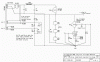
I'll be using this with several Magnavox DG modified tube amps as well as the Kegger/Blueglow SE KT88. This will be a cathode follower pre. JE Labs schematic below.
upload_2022-12-1_16-13-37.png
 
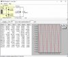
Total heater drain would be 0.6A at 12V (12SN7 plus two 76 heaters in series), so a voltage doubler from the 4A winding should work for both. 2.4A required from the 6.3V winding. Like this:

PSU4.jpg

I'd get a few resistors above and below 5.6 Ohms (5W size) - there are some estimates and simplifications that may not work out.
 
You could go with a single 6J5 per channel instead of using half of a 6SN7 per channel. Or a single 6SN7 for both channels? The 6J5's being half of a 6SN7. The 6J5's are very linier and pretty cheap. The metal ones even cheaper.
I used a single 6J5 per channel in a preamp using a UTC mic transformer at the input and Edcore 600 ohm tranies for the out put. It had a nice clean sound.
I used two 6J5's per channel in the fist 300B I built too.
 
I'll be using this with several Magnavox DG modified tube amps as well as the Kegger/Blueglow SE KT88. This will be a cathode follower pre. JE Labs schematic below.
View attachment 2728764
Is there some advantage to using a cathode follower that I'm not aware of . . . if there is no need for a lower impedance output?

That's important if you're using a SS or Class D amp or driving very long cables but it just seems like added and unnecessary complexity if those situations don't apply. What's the upside?

I've never built anything with a cathode follower so maybe I'm missing something.

I just prefer simple circuits whenever possible, I guess. When I built a preamp a while back I wanted to have the option of occasionally using it with SS and Class D. I was able to achieve a relatively low impedance output without using a cathode follower by using the 1626 whose plate resistance is quite low. It also has a 12.6v heater, BTW.

https://www.audiokarma.org/forums/index.php?threads/1626-preamp-build.931276/

The same basic circuit is often used with the 76, 6SN7 and lots of others. I didn't really need any gain but I wanted a bit "just in case". The mu of the 1626 is only 5 whereas the 76 has a mu of 13.8 and the 6SN7 family has a mu of 20.

I've got a 6J5G in my breadboarded amp and I really like it. As mentioned previously, there is a 12J5 too and they're cheap - $6 at my local dealer. I've also used the 2c22 / 7193, which is also "half a 6SN7" but it has dual top caps. I used four of them in my PP 6B4G amp instead of a pair of 6SN7s after reading many claims that the single section versions actually sound better than the duals.
 
mostly the advantage is low source impedance that doesn't care all that much what you connect it to. Most things that are not vintage tube amps really want a lower source impedance than a non-buffered tube will give you, especially a high gain tube that has fairly high plate resistance. Cathode followers are pretty invisible sonically so there really isn't any penalty to using one.
 
I would hesitate to only utilize one of the triodes in a twin triode (I know McIntosh does it) but in your circumstances you could put both triodes to work and use one fewer 6sn7s, or 12sn7s as the case may be.
If you need to keep that number of tubes for aesthetic reasons, try paralleling the cathode, plate and grid. That way they're using both sections.
Seems like using 2 tubes where one would work is pretty wasteful.
Buying an extra socket and tube for no good reason then more transformer to power it and more electricity every time you use it
I'm not trying to suggest becoming scrooge, but heating up 2 extra triodes that arent doing anything is going to cost more in many ways...
 
Last edited:
if you parallel it, just make the K resistor half the value. That should give you the same operating point as a single triode. Double the current with half the resistor = same voltage.

also make sure you've got reasonably matched triodes if you do this or it may add some distortion to the mix.
 
Is there some advantage to using a cathode follower that I'm not aware of . . . if there is no need for a lower impedance output?

That's important if you're using a SS or Class D amp or driving very long cables but it just seems like added and unnecessary complexity if those situations don't apply. What's the upside?

I've never built anything with a cathode follower so maybe I'm missing something.

Although there are many pre-amp / line stage designs all over the Internet and vintage printed articles, most of the better ones use a cathode follower or have an output impedance <1kohm. It is just good design engineering to have a low output impedance. Simple is "simple" sometimes, not better.

As gadget73 said, there is no penalty with a cathode follower, but it will ensure cables and parasitics won't degrade your signal chain.
 
I built a line stage years ago that will run with either the 76 or a 37. I based it on a design from Gary Pimm which used a CCS in the anode and the output taken from the mu follower of the CCS. That also provides a low output impedance and doesn't require the follower tube. The CCS also gets that stage to near max gain for the tube. I used the attached schematic as my inspiration.

If you want the 12SN7 for a follower, why don't you use half in each channel? Can't see that causing a problem.

John
 

Attachments

  • 85 line stage.gif
    85 line stage.gif
    102.1 KB · Views: 32
Although there are many pre-amp / line stage designs all over the Internet and vintage printed articles, most of the better ones use a cathode follower or have an output impedance <1kohm. It is just good design engineering to have a low output impedance. Simple is "simple" sometimes, not better.

As gadget73 said, there is no penalty with a cathode follower, but it will ensure cables and parasitics won't degrade your signal chain.
Perhaps I'll try adding a CF during the breadboard phase if I build another preamp at some point. I do have a couple of 10s that I've thought about using in a preamp rather than restrict their use to the front end of any one particular amp.

As for the under 1k goal, there's a rule of thumb that says the output impedance should be no more than 10% of the input impedance of the amp. So it really depends on the actual input impedance of the amp you want to drive. That's why I asked about what amps he was planning to use. As I understand it, 10k is pretty much the lowest that is commonly found in SS and Class D, hence the 1k goal.

All the tube amps I've seen have input impedances that are considerably higher than that - 100k is fairly common - but I'm sure I haven't seen everything. The grid leak resistor on the input tube determines, or is major contributor to, the input impedance, correct? Those are almost always at least 100k.

In my case, I wanted the option to use the preamp with a Yamaha SS power amp, whose input impedance is 20k, and some little Class D amps that I picked up. I haven't been able to find specs for them but I assume they're somewhere between 10k and 20k.

Based on the limited information I could find about the 1626's plate resistance, my Boogie Factor preamp has an output impedance of roughly 1.39k which quite reasonable for a simple design. As such it meets the 10% rule with the Yamaha and is at least very close when it comes to the Class D amps. It certainly sounds good with all of them and I don't use long cables so that's not a concern.

Of course there are other tubes that could also be used without a CF. The 12B4A is a good example. As I recall, it's plate resistance is around 1k and preamps using it have output impedances below that. I played around with them years ago and it's a very nice sounding tube that has very solid bass. Cheap too - $5 at my local dealer and can be heated with 12v or 6v. Lot's of schematics out there too. Not a lot of gain but most amps don't need any gain at all to make full power.

I had to retire the preamp that used them. It was just a thrown together project using the chassis of a Zenith reverb amp. I failed to notice that the PT was under-spec'd and ran way too hot. Otherwise, I'd still be using it.
 
A lot of vintage preamp used stuff like a 12ax7 though, and those just don't have very low Z output. Fine into 500k, not so much into 50k or less. Most of that was to allow tone controls and still have some overall gain.
 
If you're building from scratch, maybe consider a small 12V switching supply for the filaments. The units I've purchased were adjustable for 12.6VDC, and they hold the voltage steady as a rock.

Jack
 
If you're building from scratch, maybe consider a small 12V switching supply for the filaments. The units I've purchased were adjustable for 12.6VDC, and they hold the voltage steady as a rock.

Jack
Jack, I'm building from scratch. Would the switch be for converting from 12.6v to 6.3v for tube rolling? I'm intrigued. I think that I saw that on Valvesnmore.com's website where they used different wallwarts for the fillament supply. What in the circuit makes the voltage hold steady?
 
The units I was referring to are internally regulated. They're not wall warts, and not switchable.

Screen Shot 2022-12-03 at 9.27.28 AM.png

If you want this to be switchable, it would be much simpler to use AC on the filaments. I don't know how much hum rejection can be achieved by elevating the filaments when 12.6VAC is applied. I have a large collection of 12V tubes myself, but haven't performed the necessary testing for this.

Jack
 
Thanks for all of the input. I've got a lot of possibilities to consider. The thing I find the most interesting is that nobody recommended using half of a *SN7 - in fact the recommendations are opposite and to use both halves of the triode. That's good news - I'd rather only use one tube when one tube is needed. I guess all of photos using half of two 6SN7's was for aesthetic reasons. The 6J5 is a strong possibility. That tube is very similar to the 6SN7 but less expensive, and would make the build a lot more straightforward and simple. The transformer is a lot easier to find, too.

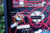
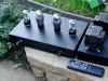
This is typical example of the use of 1/2 of the 6SN7 that I've seen so many times in my web searches. I get that glowing tubes are cool looking but this just doesn't make too much sense to me.
upload_2022-12-3_9-43-22.png upload_2022-12-3_9-47-2.png
 
Last edited:
Back
Top Bottom