• The move to the new server is done. There are some software and database maintenance updates in process. This has us passing the hat around to help out. We appreciate any donations. Seriously, even a dollar helps. The payment page may be found here - https://www.audiokarma.org/support.html

load line thoughts?

Also make sure to consider the screen current curves and the output impedance of your screen supply. At 120 volt screen you can exceed 20 mA of screen current if you get close to 0 volts grid. That's going to get even worse at higher screen voltages. This makes running a doubler supply with screen taken from the midpoint potentially appealing.
 
The transformers I'm planning to use are 6.2K primary, so performance like a 6V6 really isn't going to work well for that, hence the higher screen supply. Its a voltage doubler, pulling the screens out of the middle of the supply would be very easy but thats going to be about 200v with the plates about 400. Have to model the transformer to see exactly what its going to give but it should be in that neighborhood.

If I do a voltage other than that, it would be through an EFB regulator to keep it from being a soggy mess.
 
only reason I'm even using a resistor is I need somewhere to bring the feedback in. Plan is to share this LED for both triodes. One will be direct to the LED, the other will have a 100 in series with it. Depending on the particulars I might make that smaller just to minimize the difference in bias voltage between the two sections.
I've found an unbypassed resistor (usually ends up in the 100-300ohm range) in series with an LED sounds better than just using an LED by itself. Takes some of the edge off it.
 
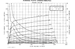
Whoops, I was totally confusing my loadlines -- my initial comment should have said 6L6, and it's really more like 300 volts on the 6L6 screen that gives curves similar to the 6LR8 with 120 volts screen. See attached screenshots. Just highlights how much more current these sweep tubes will do vs. common audio types at low screen voltage.
 

Attachments

  • 6L6 curves.png
    6L6 curves.png
    143.4 KB · Views: 9
  • 6lr8 curves.png
    6lr8 curves.png
    147.8 KB · Views: 9
yeah, it will do a decent bit of current, just need to make sure its got enough screen supply to make use of the transformers. Bit of an artifact of designing things around stuff you have vs having an optimal match.

I'll model the power transformer tonight to see what its actually capable of, that will give me a better idea of how to proceed. If I can do this without an EFB screen regulator I'm fine with that. Nothing against it, but if just pulling from the middle of the doubler will get me where I want to be I'm fine with that. Will need a choke but I think I've got something. If not its an excuse to upgrade the choke on my ST70 and recycle the one in it for a screen supply.
 
I found two chokes, one suitable for the main B+ feed, and a smaller one that will serve for the screen supply. Best info I can come up with suggests the bigger one is about 2.5H and its 60 ohms DCR. The other should be closer to 10H and its 400 ohms. Much lower current but it should be adequate for the screen supply. Don't have an LCR meter so relying on internet research here.

Looks like after the 2.5H choke in the B+ supply the feed to the output transformers will be pretty close to 432v. The 10H choke I dug up for the screen supply should put it around 217v. if I use the extra heater winding to buck the primary that should come down right about 5%, so about 410v for the plate supply and 206 for the screens. Close enough. It will lose a few volts in the transformer so it should come out close enough to 400 on the plates. Info I'm finding is that these will suffer closer to 500 without any fuss, so not going to worry too much about that. With the heater load it should also draw it down just a smidge.
 
Back
Top Bottom