• The move to the new server is done. There are some software and database maintenance updates in process. This has us passing the hat around to help out. We appreciate any donations. Seriously, even a dollar helps. The payment page may be found here - https://www.audiokarma.org/support.html

Looking to recap and convert posts on these old Motorola speakers. Seeking advice and knowledge

xcogito

New Member
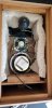
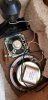
I picked up a pair of ~60s Motorola speakers with a recent TT buy. I have no idea the quality as searching comes up nearly empty. I figured I'd take the opportunity to do my first recap.

I am a little confused about what I need, as there is only a single capacitor, but it's ratings are 33 MFD 25 VNP

Through my searching, it looks like MFD might be the equivalent of uF? And the VNP means volt non-polarized? If that's the case, then I assume a 33 uF cap from parts-express will do the job? Here is what I'm looking at: https://www.parts-express.com/33uf-100v-electrolytic-non-polarized-crossover-capacitor--027-350


Lastly, these speakers need the cable replaced. One looks fine but the other looks like it melted. Not even sure of the speaker is usable, but since they were freebies in my turntable purchase, I didn't care.

I'm wanting to convert the speaker cables running out, to a banana plug female post running in. If that's not clear, I would make a cut a small hole to mount this to the back, instead of having the wire running directly out:https://www.parts-express.com/parts...ana-jack-5-way-speaker-wire-terminal--260-301

Is there any reason I should not do that?

Pic's attached

 

Attachments

  • 20201007_122904 (1).jpg
    20201007_122904 (1).jpg
    82.3 KB · Views: 44
  • 20201107_100451.jpg
    20201107_100451.jpg
    82.8 KB · Views: 46
  • 20201107_100455.jpg
    20201107_100455.jpg
    73.3 KB · Views: 42
  • 20201107_100740.jpg
    20201107_100740.jpg
    86.8 KB · Views: 44
  • 20201107_102747.jpg
    20201107_102747.jpg
    38.2 KB · Views: 42
  • 20201107_102752.jpg
    20201107_102752.jpg
    36 KB · Views: 42
Register to hide this ad
Seems like a nice, small speaker worthy of restoring. You could use some Howards Restor-A-Finish to freshen up the cabinets.

Before recapping, I would check the resistance of each driver's voice coil to ensure that there is no open circuit. Based on the condition of the wiring, it would be prudent to ensure that the drivers still function.

You are correct, MFD (microFarad) is equivalent to uF (Greek mu for micro). The cap is a first order filter for both the mid and horn tweeter.

The electrolytic cap from PE is fine for that application. I prefer to spend only what a speaker is worth when recapping. In this case, the electrolytic cap is fine.

I use the PE 5-way binding post on a lot of my speaker restoration projects. Drill two holes for the mounting tabs and route the internal wires to the tabs. Then screw the plate to the back. The posts will protrude from the back, so you need to be careful. The alternative is to cut a larger hole with a hole saw and install a round terminal cup, such as:
https://www.parts-express.com/round...fuse-holder-binding-post-banana-jack--260-293
(you don't need to use the fuse)
 
I wouldn't expect too much from these due to a couple of observations. One, the woofer and "midrange" share the same cavity. This is almost never a good idea, except in the instance of a 2.5 way design, where there are dual woofers with one also performing midrange duty. Two, the tweeter appears to have no crossover other than the capacitor that is also being used for the midrange, so you basically have both producing the same range of frequencies. I suspect this would have been better as a two-way, assuming the woofer and tweeter frequency ranges overlap, and that it was built as a three-way strictly for marketing purposes.
 
...the tweeter appears to have no crossover other than the capacitor that is also being used for the midrange, so you basically have both producing the same range of frequencies.
I'm guessing the tweeter is a piezo, which they always claimed "needs no crossover". In reality the tweeter is basically a capacitive load rather than (mostly) resistive, and it rejects low frequencies and doesn't need a capacitor to protect it from bass. I've always wondered if those tweeters could be made to perform much better by using a crossover designed for their unique impedance characteristics. So far it remains one of those projects I intend to get round to one day.
 
Looks like a typical console stereo speaker arrangement. Full range big driver, simple bass blocker cap feeding the mid and/or tweeter. Usually lots of midrange overlap since the large driver doesn't naturally roll off until well into the vocal range. A real crossover can usually improve them, the cabinet and driver quality is a limiter but even using a proper 3 way crossover to cut down on the overlap in order to flatten out the response can really make a difference. It does tend to make them less sensitive though just because you won't have 3 drivers trying to reproduce 1khz notes.
 
I'm guessing the tweeter is a piezo, which they always claimed "needs no crossover". In reality the tweeter is basically a capacitive load rather than (mostly) resistive, and it rejects low frequencies and doesn't need a capacitor to protect it from bass. I've always wondered if those tweeters could be made to perform much better by using a crossover designed for their unique impedance characteristics. So far it remains one of those projects I intend to get round to one day.
Yeah, that did occur to me, but I thought that the end cap was larger than a piezo typically needs. You're probably right, though. Your thoughts about crossing piezos over in general are right on the money per other threads I've read here. Generally the recommendation is to wire an 8Ω resistor of sufficient wattage in parallel with the piezo, then cross it over as you would a standard driver.
 
Back
Top Bottom