• The move to the new server is done. There are some software and database maintenance updates in process. This has us passing the hat around to help out. We appreciate any donations. Seriously, even a dollar helps. The payment page may be found here - https://www.audiokarma.org/support.html

Low Volume on FM- Need Tech Help

BigShooter

New Member
Hopefully there are a few techs here that can give me some direction...
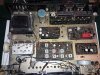
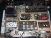
I have an Allied 445 receiver that has severely reduced volume (about half) on FM and FM mono only (I got it this way). Volume is normal on AM, aux, and phono. Also, there is no FM stereo light on when on FM stereo selector position (replaced with LED), and music is not played in stereo on FM. The low volume on FM is present whether I use speakers or headphones. I do not have, and cannot find, a schematic for this unit, so I cannot identify which PCB does what on this unit (I'm very new to this). I've included a photo of the chassis, so if you can tell me what board does what, and specifically, what board(s) are related to the FM circuit, that would be very helpful. Please give me some guidance here. TIA for sharing your knowledge.
 

Attachments

  • Allied 445.jpg
    Allied 445.jpg
    190.6 KB · Views: 28
Register to hide this ad
IIRC, this receiver uses a rather infamous Intermediate Frequency IC in the FM section, well-known for failing and causing this complaint. Again, its IIRC (because I left Radio Shack about 1978) there are 3 or 4 of them on the FM IF board. They are black epoxy and round, maybe about 3/8" in diameter, but have 6 or 8 legs rather than 3 that you see on a transistor. To determine which is bad, take a 0.01uf disk cap, and put it from one end of the part to the other (input to output). If its a good part the FM will get even quieter, but if its a bad one the volume will increase. I suspect they used this part simply because RF gain on SI transistors at the time wasn't all that great. But who knows...

Seems to me there is or was an ECG/NTE replacement IC for this but without the original part number google isn't finding it. If you posted an internal photo of the topside of the receiver, I could point out which is the IF board with these ICs.
 
If this is similar to the IC used in some Sansui tuners, I've gotten very usable substitutes on the 'bay. It just takes some searching around and research to figure out which one will work.
 
IIRC, this receiver uses a rather infamous Intermediate Frequency IC in the FM section, well-known for failing and causing this complaint. Again, its IIRC (because I left Radio Shack about 1978) there are 3 or 4 of them on the FM IF board. They are black epoxy and round, maybe about 3/8" in diameter, but have 6 or 8 legs rather than 3 that you see on a transistor. To determine which is bad, take a 0.01uf disk cap, and put it from one end of the part to the other (input to output). If its a good part the FM will get even quieter, but if its a bad one the volume will increase. I suspect they used this part simply because RF gain on SI transistors at the time wasn't all that great. But who knows...

Seems to me there is or was an ECG/NTE replacement IC for this but without the original part number google isn't finding it. If you posted an internal photo of the topside of the receiver, I could point out which is the IF board with these ICs.
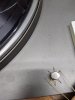
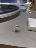
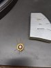
I remember them as UA703 ic. a 6 pin device that came as a metal can, or a epoxy blob. The metal one had a tab aligning with the center pin of a set of 3, with 3 more similar pins on the other side. The epoxy blob usually had a white spot of paint where the center pin of 3 was. I would use a small value cap (I usually used an orange mylar with long leads). Listening with headphones, I would jumper pins diagonal (left most pin on the top set of 3 to the right most pin on the bottom set of 3), and then (right most pin on top 3 to left most pin on bottom 3). If the level stayed the same or decreased on any of these 2 tests, the IC was probably fine. If the level increased noticably, on either test, then the ic was probably bad and should be replaced. see pictures
ua703 cap jumper.jpg ua703 test 2.jpg UA703 top.jpg ua703.jpg
 
IIRC, this receiver uses a rather infamous Intermediate Frequency IC in the FM section, well-known for failing and causing this complaint. Again, its IIRC (because I left Radio Shack about 1978) there are 3 or 4 of them on the FM IF board. They are black epoxy and round, maybe about 3/8" in diameter, but have 6 or 8 legs rather than 3 that you see on a transistor. To determine which is bad, take a 0.01uf disk cap, and put it from one end of the part to the other (input to output). If its a good part the FM will get even quieter, but if its a bad one the volume will increase. I suspect they used this part simply because RF gain on SI transistors at the time wasn't all that great. But who knows...

Seems to me there is or was an ECG/NTE replacement IC for this but without the original part number google isn't finding it. If you posted an internal photo of the topside of the receiver, I could point out which is the IF board with these ICs.

See my original post, I did post a photo. Would you need a close up or different photo?
 
I remember them as UA703 ic. a 6 pin device that came as a metal can, or a epoxy blob. The metal one had a tab aligning with the center pin of a set of 3, with 3 more similar pins on the other side. The epoxy blob usually had a white spot of paint where the center pin of 3 was. I would use a small value cap (I usually used an orange mylar with long leads). Listening with headphones, I would jumper pins diagonal (left most pin on the top set of 3 to the right most pin on the bottom set of 3), and then (right most pin on top 3 to left most pin on bottom 3). If the level stayed the same or decreased on any of these 2 tests, the IC was probably fine. If the level increased noticably, on either test, then the ic was probably bad and should be replaced. see pictures
View attachment 1873057 View attachment 1873058 View attachment 1873059 View attachment 1873060

Might those be the two cans on the PCB next to the transformer that have a metal heat sink (???) on them? I don't know what board that is. If so, how would I troubleshoot them? TIA.
 

Attachments

  • Allied 445.jpg
    Allied 445.jpg
    190.6 KB · Views: 32
No they are part of the regulator power supply. Look at the board on the bottom of your picture in the middle. There are 8 metal "IF" transformers (cans) on the board. I see what looks like 2 of the suspect IC's on the bottom inbetween cans on that bottom row.
 
No they are part of the regulator power supply. Look at the board on the bottom of your picture in the middle. There are 8 metal "IF" transformers (cans) on the board. I see what looks like 2 of the suspect IC's on the bottom inbetween cans on that bottom row.

Thanks for your comments. When I look at the actual PCB I see that there are six leads on the bottom. So this is an IC? OK, are they easy to test? In other words do they all test the same way, or do I need to identify them to learn the pinout, like testing a transistor? Does the method of jumping them with a capacitor to check for increased volume work on these? If so, how do I know what ones to jumper? Any help is appreciated.
 
Thanks for your comments. When I look at the actual PCB I see that there are six leads on the bottom. So this is an IC? OK, are they easy to test? In other words do they all test the same way, or do I need to identify them to learn the pinout, like testing a transistor? Does the method of jumping them with a capacitor to check for increased volume work on these? If so, how do I know what ones to jumper? Any help is appreciated.

This is a bit of a ride down memory lane... as I mentioned, you only need a 0,01uf cap with long leads to test the ua703s. Jumper as mentioned by me and @Tom B (Tom gave more detail on that), while the unit is running. Don't allow the leads of the cap to touch anything else of course; you have to be playing the FM... If jumpering the IC causes a loss of signal, its good, if the signal increases, that's your bad IC (the cap is allowing the signal to bypass the IC). Jumper to opposite sides; so there are three ways the cap can be connected since you are looking at pins that are opposite of each other. If the IC is bad one of those three ways will yield an increase in volume. When I worked at the RS service center we fixed a lot of these and finding the bad IC on the IF board was only an affair of a minute at the most.
 
This is a bit of a ride down memory lane... as I mentioned, you only need a 0,01uf cap with long leads to test the ua703s. Jumper as mentioned by me and @Tom B (Tom gave more detail on that), while the unit is running. Don't allow the leads of the cap to touch anything else of course; you have to be playing the FM... If jumpering the IC causes a loss of signal, its good, if the signal increases, that's your bad IC (the cap is allowing the signal to bypass the IC). Jumper to opposite sides; so there are three ways the cap can be connected since you are looking at pins that are opposite of each other. If the IC is bad one of those three ways will yield an increase in volume. When I worked at the RS service center we fixed a lot of these and finding the bad IC on the IF board was only an affair of a minute at the most.

Excellent. I will give it a try. Thank you very much for your help.
 
Back
Top Bottom