

GnatGoSplat
New Member
Years ago, I bought a Luxman GX-101 equalizer to add dancing lights to my RX-103/KX-102 system. I wanted to have it come on with the system, so I plugged it into switched power on the receiver. To my disappointment, it could not remember settings when disconnected from power for more than a day, and worse, it defaults to displaying EQ levels and not spectrum analyzer.
I've seen at least one post on this forum that the GX-101 is common to have a bad memory circuit. After disassembling my GX-101, I came to learn the memory circuit isn't bad; it just doesn't exist. There are no batteries, no super capacitor, no EEPROM (probably too old for EEPROMs). It has a standby voltage that's present at all times as long as it stays plugged into power. It was clearly not designed to be used on a switched outlet, but I'm too lazy to manually switch it on and off, so I decided to build a memory keep-alive circuit.
Disclaimer: I am not an EE. I have no electronics training. If you are an EE, you will likely find much to criticize in this post.
Standby Schematic and adding a Super Cap Memory Backup
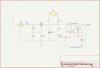
First, I started by mapping a schematic of the existing standby power supply. Approx 15VAC from the power transformer is rectified by discrete rectifier diodes, then passed through a 7812 12V 1A voltage regulator IC (Q101). This is then dropped down to +5V by a transistor-zener regulator (TR101, D104). Filter cap C104 stores just enough charge to keep the MCU powered up for about 1-day. I put my multimeter in mA mode and was able to determine the 4013 IC and MCU together use about 2mA and MCU alone uses less current than would even register on my meter. Seeing as how the load is very small, I decided to go with a super capacitor for its simplicity and life span. Here is the schematic of the standby power supply and in the dashed lines is my super capacitor circuit.
I searched Google for different super capacitor circuits, but the simplest of all was the one used in the Technics SH-8046 membrane-touch equalizer. I've owned one of these since 1988 and its memory circuit works fantastically. Its manual states it may lose memory after being unplugged a week, but I've literally had it sit for 5+ years and still keep its memory. It effectively only has a 1.65F super cap (2x 3.3F in series). My circuit is pretty much the same as the Technics. I chose a 10F super cap because I didn't know at the time what size they used in the Technics and I figured 10F should be big enough. Supercap C1 charges through Schottky Diode D2 and series current limiting resistors R1 and R2. They are effectively 50-ohm to limit startup charging current to 100mA because the 2SC1815 (TR101) transistor has an Ic of 150mA max. I could have used a single 50-ohm 1/2W resistor, but I used 2x 100-ohm 1/4W because that's what I had available (much more common). When power is cut off, supercap C1 powers the MCU through Schottky diode D1. D2 prevents C1 powering the 4013 IC. Both diodes are Schottky to reduce voltage drop (approx 0.175V instead of the usual 0.6V), and the part #s are unimportant; they are just what I had in my junk bin.
Implementation
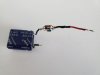
Here is the finished circuit sans D2. It's easier to assemble the whole thing with D2 in place and just solder that to the PCB, which I had done initially, but I decided to change my series resistance so I had to pull it apart and try again.
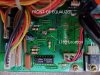
I chose to tap into jumper J163 because it supplies power to only the MCU. For the sake of memory keep-alive, powering 4013 IC is unnecessary. J163 acts as a via to the traces on the other side since this board doesn't use through hole plating. This is the location of J163 on the top of the power supply PCB.
On the underside of the PCB. You can also see the MCU. Very interesting that it's on the power supply PCB.
First, I removed/discarded jumper J163. Then I soldered my D2 diode's anode lead directly to the solder pads, being sure it's bent in such a way it can also be soldered to the large pad in the center as that's actually where the power comes in. I ran the cathode lead through a nearby existing hole and bent it to solder onto the solder pad. Reason I didn't just put it through the solder pad hole is I didn't want the top solder pad shorting to the bottom one. A short there would bypass the diode. It's not plated through, but the top solder pad would be literally micrometers from touching the diode lead. Since there was a nearby hole, I just decided to use that and remove all risk.
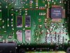
I've soldered capacitor cathode to the nearest ground: jumper J172. In this image, you can see my diode D2 soldered in place of jumper J163. My super cap circuit is soldered to the cathode lead of D2.
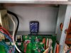
I didn't bother to insulate the other components as the component leads are pretty stiff and they're over 1/2" away from touching anything. No way they will short. Also I didn't want to shrink wrap over them in case years later I open the EQ, I might not remember what I did. The super cap is double-side taped to the bottom of the case.
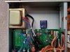
So far, it's working great. I've let it go disconnected from power a full week and memory is still retained. I have no idea how long it could go, but I seldom go more than a week without using the stereo so I'm quite happy with it. Total cost was $7-ish for the capacitor and rest of the parts came from my junk bin.
I've seen at least one post on this forum that the GX-101 is common to have a bad memory circuit. After disassembling my GX-101, I came to learn the memory circuit isn't bad; it just doesn't exist. There are no batteries, no super capacitor, no EEPROM (probably too old for EEPROMs). It has a standby voltage that's present at all times as long as it stays plugged into power. It was clearly not designed to be used on a switched outlet, but I'm too lazy to manually switch it on and off, so I decided to build a memory keep-alive circuit.
Disclaimer: I am not an EE. I have no electronics training. If you are an EE, you will likely find much to criticize in this post.
Standby Schematic and adding a Super Cap Memory Backup
First, I started by mapping a schematic of the existing standby power supply. Approx 15VAC from the power transformer is rectified by discrete rectifier diodes, then passed through a 7812 12V 1A voltage regulator IC (Q101). This is then dropped down to +5V by a transistor-zener regulator (TR101, D104). Filter cap C104 stores just enough charge to keep the MCU powered up for about 1-day. I put my multimeter in mA mode and was able to determine the 4013 IC and MCU together use about 2mA and MCU alone uses less current than would even register on my meter. Seeing as how the load is very small, I decided to go with a super capacitor for its simplicity and life span. Here is the schematic of the standby power supply and in the dashed lines is my super capacitor circuit.
I searched Google for different super capacitor circuits, but the simplest of all was the one used in the Technics SH-8046 membrane-touch equalizer. I've owned one of these since 1988 and its memory circuit works fantastically. Its manual states it may lose memory after being unplugged a week, but I've literally had it sit for 5+ years and still keep its memory. It effectively only has a 1.65F super cap (2x 3.3F in series). My circuit is pretty much the same as the Technics. I chose a 10F super cap because I didn't know at the time what size they used in the Technics and I figured 10F should be big enough. Supercap C1 charges through Schottky Diode D2 and series current limiting resistors R1 and R2. They are effectively 50-ohm to limit startup charging current to 100mA because the 2SC1815 (TR101) transistor has an Ic of 150mA max. I could have used a single 50-ohm 1/2W resistor, but I used 2x 100-ohm 1/4W because that's what I had available (much more common). When power is cut off, supercap C1 powers the MCU through Schottky diode D1. D2 prevents C1 powering the 4013 IC. Both diodes are Schottky to reduce voltage drop (approx 0.175V instead of the usual 0.6V), and the part #s are unimportant; they are just what I had in my junk bin.
Implementation
Here is the finished circuit sans D2. It's easier to assemble the whole thing with D2 in place and just solder that to the PCB, which I had done initially, but I decided to change my series resistance so I had to pull it apart and try again.
I chose to tap into jumper J163 because it supplies power to only the MCU. For the sake of memory keep-alive, powering 4013 IC is unnecessary. J163 acts as a via to the traces on the other side since this board doesn't use through hole plating. This is the location of J163 on the top of the power supply PCB.
On the underside of the PCB. You can also see the MCU. Very interesting that it's on the power supply PCB.
First, I removed/discarded jumper J163. Then I soldered my D2 diode's anode lead directly to the solder pads, being sure it's bent in such a way it can also be soldered to the large pad in the center as that's actually where the power comes in. I ran the cathode lead through a nearby existing hole and bent it to solder onto the solder pad. Reason I didn't just put it through the solder pad hole is I didn't want the top solder pad shorting to the bottom one. A short there would bypass the diode. It's not plated through, but the top solder pad would be literally micrometers from touching the diode lead. Since there was a nearby hole, I just decided to use that and remove all risk.
I've soldered capacitor cathode to the nearest ground: jumper J172. In this image, you can see my diode D2 soldered in place of jumper J163. My super cap circuit is soldered to the cathode lead of D2.
I didn't bother to insulate the other components as the component leads are pretty stiff and they're over 1/2" away from touching anything. No way they will short. Also I didn't want to shrink wrap over them in case years later I open the EQ, I might not remember what I did. The super cap is double-side taped to the bottom of the case.
So far, it's working great. I've let it go disconnected from power a full week and memory is still retained. I have no idea how long it could go, but I seldom go more than a week without using the stereo so I'm quite happy with it. Total cost was $7-ish for the capacitor and rest of the parts came from my junk bin.

