

You are using an out of date browser. It may not display this or other websites correctly.
You should upgrade or use an alternative browser.
You should upgrade or use an alternative browser.
Luxman LX-104 Suckface Microswitch
- Thread starter craigsc
- Start date

SmileyFaceEQ
Super Member
I was able to finally find a way to replace the microswitch in my LX-104 with a currently available part. I used an OMRON D2HW-C221H. I did have to modify the OMRON part a bit to get it to work. If you need a part the Fuxtor I can modify one and send to you. I bought a few extra switches. PM me.
Dude, thanks for the part number. Mine was totally missing. Someone else had broken it i guess. Can you offer any advice on how you modified the switch?

craigsc
Active Member
I can’t find any pictures of what I did or really remember it exactly!! I think I basically need to trim the plastic case of the micro switch to get it to sit squarely in the spot where the original switch would have been. If you send me a couple of pictures it might help me remember.
SmileyFaceEQ
Super Member
The three wires coming from the motor......red, brown, green.....connecting the brown and red wires actives the motor. I am assuming the green wire is a ground? Anyone know what purpose the green wire serves? I replaced the belt and everything works aside from the fact that the switch is missing.
The unit operates flawlessly. The original owner must have attempted a belt replacement and broke the switch.
How would I go about wiring the mechanism via the front panel button? Is it via the power switch I was considering adding a button to hold to retract the face on the side of the case, but I think it can saved.
The unit operates flawlessly. The original owner must have attempted a belt replacement and broke the switch.
How would I go about wiring the mechanism via the front panel button? Is it via the power switch I was considering adding a button to hold to retract the face on the side of the case, but I think it can saved.
SmileyFaceEQ
Super Member

The circuit that controls the servo mechanism.....
red / brown complete the power circuit. The green wire powers a capacitor c638 via q633 which stays open (on) under power . When the power is switched off c638 dumps via q632 (voltage reg) and bumps the switch over just enough to release the catch on the cam connected to the brass flywheel and returns the face plate to flush over the buttons.
So, if you just wanted to "manually" operate the face plate, you can neglect the green wire and microswitch and just install a switch on the case and push and release it.
I have decided to try the microswitch repair first. If not successful, then ill just add a small pressure switch on the right hand side. Holding it to retract the face and releasing it before the cam cycles over and releases the mech.
This video from a retired tech from B.C. does a good job explaining the mech and fixing a kx
Last edited:

The Fuxtor
Addicted Member

SmileyFaceEQ
Super Member
Since I have the mech mostly working now I have started looking at the kx tape decks. Same mech just slightly different disassembly.

Milton D
New Member
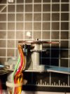
Seems I am a bit late to this thread. Did you manage to modify the omron switch? If so, how did you do it. The switch is 5.3 mm wide which is around double the thickness of the old switch. Did you end up sanding down the mounting hole area for it to sit lower down? I have attached an image the original switch position. (I managed to tear the living hinge when reassembling the mechanism)Since I have the mech mostly working now I have started looking at the kx tape decks. Same mech just slightly different disassembly.
Attachments
Milton D
New Member
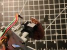
I managed to retrofit the aforementioned Omron switch to the mechanism. Here is what I have learned.
-Cut about 5mm off of the lever
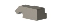
-The original screw head for the microswitch fits inside of the m3 hole in the Omron switch acting like a pivot. A 3d printed support was required to hold the switch at the desired angle. (image attached) The armature fits around the back of the bridge that holds the switch.
- Premature actuation of the switch can be avoided by making sure it fits snugly against the support.
I will probably remodel the support so it acts as a more rigid mount for the switch, for the time being I am sick of looking at this mechanism. It works just fine now.
Please message me if you want a model of the support. I will try to improve it in my spare time, it is definitely a little crude at this point.
-Cut about 5mm off of the lever
-The original screw head for the microswitch fits inside of the m3 hole in the Omron switch acting like a pivot. A 3d printed support was required to hold the switch at the desired angle. (image attached) The armature fits around the back of the bridge that holds the switch.
- Premature actuation of the switch can be avoided by making sure it fits snugly against the support.
I will probably remodel the support so it acts as a more rigid mount for the switch, for the time being I am sick of looking at this mechanism. It works just fine now.
Please message me if you want a model of the support. I will try to improve it in my spare time, it is definitely a little crude at this point.
Attachments
SmileyFaceEQ
Super Member
What switch did you go with? I have 2 units now that need this repair.
1) rx-101
2) kx-101
I would happily buy 2 of these supports from you.
1) rx-101
2) kx-101
I would happily buy 2 of these supports from you.
SmileyFaceEQ
Super Member
No. It is a skill that I currently do not have. It is frustrating because I have the px-101 turntable as well. So the entire set. 2 non functional faces. I did install a momentary switch as a work around, but it leaves me dissatisfied.I used the Omron D2HW-C221H. Craigsc mentioned it earlier in the thread. The mechanism should be the same for all of the suckface units. I want to try and improve the design a little more before I start selling them. Do you have access to a 3d printer?

Henninge
New Member
These amps exemplify the connection between digital and analog and I am a design historian and so I know. You simply do not know anything other than your old 1070's biased opinion."SuckFace" has also been described for amps and receivers that were just plain "Fugly".
The Fuxtor
Addicted Member
Any updates on that switch?? I have a couple units with broken switches still
Suckface refers to a front panel in which the knobs & switches ride on a motorized sled. When the piece is powered up the sled moves forward, exposing the controls. When the piece is turned off, the sled slides backward so that the control knobs are flush with the front panel's surface. It's a gimmick that has no real practical value. Looks cool, though.Sorry, but what’s a “suckface” anyway, please?
any chance I could get the print file from you? I would be happy to pay, I have the omron switch but would prefer to pay rather than spending a couple hours to mock up my own design. Even if you don't have a "updated" design I don't mind, I don't care if it is ugly as long as it works.I managed to retrofit the aforementioned Omron switch to the mechanism. Here is what I have learned.
-Cut about 5mm off of the lever
-The original screw head for the microswitch fits inside of the m3 hole in the Omron switch acting like a pivot. A 3d printed support was required to hold the switch at the desired angle. (image attached) The armature fits around the back of the bridge that holds the switch.
- Premature actuation of the switch can be avoided by making sure it fits snugly against the support.
I will probably remodel the support so it acts as a more rigid mount for the switch, for the time being I am sick of looking at this mechanism. It works just fine now.
Please message me if you want a model of the support. I will try to improve it in my spare time, it is definitely a little crude at this point.

MegaHurts
Super Member
Suckface repairs suck for sure. Belt is easy enough but that micro switch that people break attempting to do belt repair is another story.
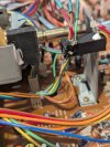
Managed to repair on switch that had broken solder tab on a RX-101 and went to fix the RX-101 cassette where half the micro switch was missing. Tried a pushbutton toggle but that doesn't work in practice because it cuts power before closing contacts to bump/close on power off. I even tried to open the switch and get it closer without success. The pic of the red pushbutton toggle has wires off to check continuity/voltage.
Ended up modifying the orig switch and moving it with 3d printed brackets. Fit has to be pretty bang on to work properly, the whole mechanism moved back to operate the switch now instead of on the copper snail gear thing.
Will have to check on the omron switch as a better method as this is kind of ugly but I'm more concerned with it's durability. At least it's working.
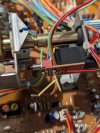
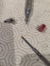
Managed to repair on switch that had broken solder tab on a RX-101 and went to fix the RX-101 cassette where half the micro switch was missing. Tried a pushbutton toggle but that doesn't work in practice because it cuts power before closing contacts to bump/close on power off. I even tried to open the switch and get it closer without success. The pic of the red pushbutton toggle has wires off to check continuity/voltage.
Ended up modifying the orig switch and moving it with 3d printed brackets. Fit has to be pretty bang on to work properly, the whole mechanism moved back to operate the switch now instead of on the copper snail gear thing.
Will have to check on the omron switch as a better method as this is kind of ugly but I'm more concerned with it's durability. At least it's working.