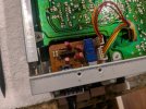
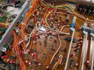
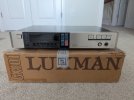
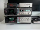
• The move to the new server is done. There are some software and database maintenance updates in process. This has us passing the hat around to help out. We appreciate any donations. Seriously, even a dollar helps. The payment page may be found here - https://www.audiokarma.org/support.html

Luxman Suck Face Stack - My Restoration

I said good receiver.

Check the 3rd post here... I'm guessing you'd consider a G9000 a 'good' receiver. This entire thread is a good read, I'm surprised more people haven't experienced input crosstalk.

I need to test the RX-103 for it when I recap it!
 
Last edited:
Recapping the GX-101 (Post 1/2):

Ok, so the Mouser order arrived on Friday, and I was quite excited to go ahead and get started, so I began the recap last night, and finished it (with one caveat) this morning. There were 5 PCBs to recap, so I placed 4 separate Mouser orders based on 4 projects I had created on my account. I did it this way as I wanted each order separated by PCB so I wasn't getting confused with a huge bag of capacitors I had to split up myself. It ended up costing me more in shipping, but it was worth it to me. I also over-ordered on each cap value as I don't have any capacitors in-stock and I wanted a generous helping left over for oversight and as a buffer for future projects. This alone drove up the cost by ~30%, but I've got a good overstock now.

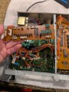
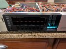
So, here is the GX-101 setup on my workspace, ready for recapping! (I am holding it up so you can see the face) I don't have a nice workbench or anything, I just repurpose my kitchen island. It has just enough space to spread out my tools/equipment needed for the job. Forget about being referred to as a 'garage technician', I am a kitchen island tech.

PXL_20250131_214038829.MP.jpg


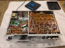
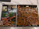
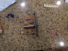
I wanted to start with the power supply, as it is the most interesting to me (cap fitment wise). There is an interface board for the LCD analyzer covering about 1/3rd of the power board, so I needed to remove that. Not difficult, just a lot of plugs to undo. Since some of the plugs were the same, I used different color marking pens so I wouldn't confuse them. I also went ahead and removed the front face and the bottom cover as well. Having the bottom exposed will be great for accessibility, as I can recap the power/main boards without actually taking them out... at least, that's the plan.

PXL_20250131_214641120.MP.jpgPXL_20250131_215541853.jpgPXL_20250131_214955998.jpgPXL_20250131_215106004.jpg

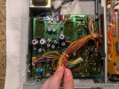
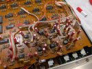
So here, we can finally see the entire power board. It's not too complicated, but there are all of the larger caps here that you won't find in the rest of the unit. Now, for 90% of the caps in this unit, and in the other components, you don't need to measure them. Most standard value caps are about 5mmx11mm in size with about a 2mm gap between legs, so when you go to Mouser to make an order, just be aware of that and ballpark it. BUT, for this power supply, it was important to get the measurements exact, because if the power caps are too wide, they won't fit. If they were too thin, it would look cheap... and I don't want that.

PXL_20250131_215551850.jpg

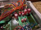
So, the new caps went in really well, I was able to avoid taking out the board as I said by just removing the bottom cover. It made my life so much easier doing it this way. I am pleased with how nice the new caps look, and the measurements were pretty much spot on. All that red is kinda pretty, ya know? It's not pictured here, but I added some hot glue around the larger caps to keep them from getting out of hand during transport.

PXL_20250131_232736078.jpgPXL_20250131_232905113.jpg

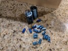
Here's the lot of caps I removed. Not many for the power board to be honest, but a good warmup for the main attraction I was facing next. About 4 of the caps on this board showed visible signs of leakage & had bad chemical smells when reheated. Nice to think of having new in-spec capacitors providing clean power!

PXL_20250131_233438123.jpg

Finally, Here's something I always do to keep myself sane. Everytime I recap a board, I put the unit back together enough to properly test it before moving on to the next board. This allows you to troubleshoot the work you just did and identify problems at a board level. If you recapped everything and tested at the end, you'd have no idea where the problem in your work was. (I've been down this road before, not fun). This same technique applies to writing code. Anyways, it still powered on at this point, nothing blew up, so I moved on to the processor board next.

PXL_20250201_000355194.jpg
 
Last edited:
Recapping the GX-101 (Post 2/2):

Next, I turned my attention to the Processor Board... or at least, based on all of the chips on this board, that's what I'm calling it. Here's what the caps look like on this board. A lot of those 10uf 16v caps that are leaky and stinky when removed. This board was even easier than the last because the entire board can be leaned out of the unit after undoing 4 screws. No disconnecting of wires needed.

PXL_20250127_033730118.MP.jpg
...and here's what it looked like after the recap was done. Again, really love the red caps, and they all seem very high quality to me... not too worried about the longevity, I'm sure they'll last for a good long time. By now, you can probably tell what the caveat is that I mentioned a moment ago; Those orange caps are the ELNA 'low leakage' variety, and I don't have those in-stock, or did Mouser. Some folks say you can use WIMA film caps as a replacement, but these are polarized, and most film caps aren't. Whatever the case is, I ordered up some Nichicon Pure Golds on eBay that have yet to show up. Those will work a treat. I don't think I'll post an update about them.

PXL_20250201_014356916.jpg

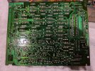
I don't normally do this, but here's what my actual soldering work looks like on the bottom of this board. I don't think I'm bad at soldering, but I'm sure I would draw many criticisms still the same. I don't really think you can tell a big difference between the original caps and their joints vs my new ones. At this point, I always go back over my work to make sure there are no shorts, and also that the caps are all in the right way. I check for the orientation both when I place the cap, and when I am finished with the solder work. Also, I place all the caps and bend their legs before doing any soldering.

PXL_20250201_013724349.jpg

So, we can see now how the final recap is beginning to take shape! All that red, looking quite sharp I must say. ...and I'm not a professional, but I don't think a shop technician would take this apart and scoff at my work.

PXL_20250201_014416945.jpg
Before moving to the main board, I did quickly take out the mic mixer board and change out those caps as well. Again, just looking at that standard 5mmx11mm size, so nothing special here. This mic is designed for the autoEQ feature, so that the pink noise played when activating autoEQ can be heard and the EQ can be adjusted. It's a flaky feature but high tech for the time I suppose.

PXL_20250201_033758607.jpg

Here's the main board after I recapped it. I couldn't find the photo I took of it before hand, but you can see how it turned out after! As mentioned, I didn't take this board out, I only accessed the solder joints from the underside of the unit with the cover removed. You can also see that I did have some of those Pure Gold caps on hand as replacements for those orange ELNA ones. I'm told those are obsolete now, but Nichicon was making them not too long ago. (Yes, I realize the pure gold audio quality thing is snake oil, but I chose them anyway)

PXL_20250201_150807181.jpg

So that's it! The graphic EQ went back together perfectly, and it works flawlessly! I didn't really notice any changes in the sound, but nothing broke so I'll consider this a success! I will say that the spectrum analyzer now actually does something... before the recap, only the loudest signals would even register on it. I'm considering this totally restored. Also, it doesn't smell bad when it warms up any longer, so that's nice. I had more photos I would have liked to post, but AK only allows 10 per post it seems, and my imgur/pinterest links were not working either.

PXL_20250201_154615885.jpgPXL_20250201_215451664.jpg

Thanks for reading! Cassette is next, so stay tuned....
 
Last edited:
I have personally never had great experiences with Luxman, or Onkyo. Although, I know many here that are fans of both brands and have had absolutely stellar experiences with them. :idea:
 
Welp, I wanted to get into recapping the the KX-102, but alas, I was sidetracked by another more important issue.

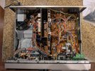
I mentioned in my original post that the KX-102 had been making squeaking sounds on and off since I got it, but these squeaking sounds started becoming louder and more annoying to me. It reached a point last week where it was so loud you could hear it in other rooms of the house! So, before devoting any time to the electronics restoration, I decided to crack it open and solve for the noise problem. There's a lot going on inside of this tape deck, and I was delighted to see that it had more metal & electronics guts than I realized. Quality on the outside, quality on the inside.

PXL_20250111_204044313.jpg

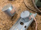
It took me all of a few minutes to find out what was making the squeak... and it wasn't a pulley or belt problem as I thought initially, but rather... it was the motor. When running the motor without any belts connected, the squeak was even louder, and the entire motor sounded like it was full of rocks. Clearly, this motor was shot, and there was no amount of oil that could fix it.

PXL_20250206_204739266.MP.jpg

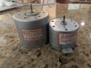
The part number for the original motor is a Mabuchi EG-510ED-2B2. It's a 12v motor that runs at 2400rpm and has an internal speed governor that turns the shaft counter clock-wise. I tried searching the internet for this part number and came up dry on all of my favorite parts websites + eBay. Clearly, it's an obsolete motor that isn't available anymore. I was beginning to really lose hope here, but some deep internet searching revealed that there is a modern substitute for this part, the Mabuchi EG-530AD-2B. Not only is this new motor readily available online, they can be had in packs of 2 for around $10... quite cheap I must say.

I realize that the new motor is much smaller in physical dimensions than the original, and I also know that this replacement motor is probably not a 'genuine' Mabuchi part, but rather, a Chinese knockoff made to the same specifications. Nevertheless, The new part seems quite decent, and given the mounting holes and shaft diameter are the same, I got the pulley transferred to it from the old motor and mounted it in.

PXL_20250206_204746079.jpgPXL_20250206_204829965.MP.jpgPXL_20250206_204833889.MP.jpg

The original motor was hardwired, and the new one has solder points, so I just clipped of the wires of the original, stripped them, and soldered them to the new motor to keep it looking original. I installed it without a hitch and it looks factory.

PXL_20250206_205708873.jpgPXL_20250207_013639207.jpg

When I initially tested a tape with the new motor installed, music was playing about a entire musical half step too high... a quick adjustment of the pot around back of the motor corrected this. Now, it is playing at the right speed/pitch, and I don't detect any noticeable wow/flutter increases from the original. It actually sounds smoother than the original when it was squeaking.

The motor is buttery smooth, both on belts and off. It has an soft acoustic hiss/buzz noise you can hear that wasn't present with the original... I guess all of that shielding in the original's larger case helped to dampen acoustic noise.

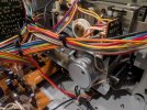
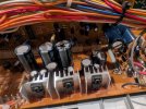
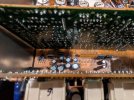
Finally, I leave you with a sneak preview of some of the capacitors I'll be changing very soon.

PXL_20250207_013925781.MP.jpgPXL_20250207_013933553.MP.jpgPXL_20250207_013945196.jpg
 
Last edited:
Have come close to buying suck face units many times. Love the looks of them/
 
Let's continue on the KX-102 Restore.
Now, it's been taking me a lot longer to do this restore than I thought, and it's not because I've been working hard on it. Rather, the unit has been apart collecting dust and I've been just waiting on all the parts to show up that I ordered. I've had to buy a lot of parts from Germany, China, and the UK.
  • Purchased a special belt kit from Amazon that has exact fit suck face belt and cassette belts.
  • Purchased a replacement custom idler tire from Germany (take up reel slipped).
  • Bought special non-polar nichicon MUSE green capacitors for all bipolar caps from the UK.
  • Had to get some of the Nichicon Fine Golds from China. (Checked for correct capacitance and authenticity)
  • Ordered the usual standard value caps from Mouser.
  • Ordered a new micro switch for the suck face.
So, it's taken a long time and still some of the caps are in transit. I'm throwing a ton of parts at this thing, hoping to see the creaks, squeaks, and little issues disappear.

But, I really want the suck face to work on this deck, and I decided to purchase a belt kit that included the right thickness and diameter of belt. My problem with the suck face was that it made an abnormal howling noise and sometimes it was too weak to suck in or recoil back when powered down. The noise alone was enough to make me disable it. But, I decided to do a full rebuild of it and took it apart again and replaced my generic belt with a custom part:

PXL_20250212_003950966.jpgPXL_20250212_004122850.jpg

As you can see, the new belt is a perfect fit, and has good stretchiness to it. I used this Amazon kit sold by Bob's Vintage Audio Parts:

Anyways, I put some grease around the cam/planet gears to hopefully stop the noise, and reassembled the mechanism... unfortunately, I did what many others have done, I broke the micro switch:

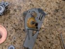
PXL_20250212_142803084.jpg

This switch is tiny, measuring only 12mm long. One of the poles broke off, and I wasn't even being that rough with it. I was gutted initially, because I had already read of folks having a difficult time sourcing a replacement. I did find one that worked ok, it was the OMRON D2HW-C221H. It is available from Mouser.

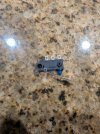
PXL_20250215_204617531.MP.jpg

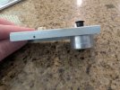
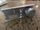
It's a good bit bigger than the original... maybe 20% longer, and it's 5.3mm thick instead of the 3mm of the original. Now. It will not fit in between the cam and the assembly unless you Dremel off the peg facing the side of the cam and also shorten the metal arm to be flush with the edge of the switch case. Finally, the screw hole is much too big, but you can jam the entire screw head in the hole tightly, and then I made a little metal stabilizer that screws to the case which I attached onto the other peg I didn't have to Dremel. This stabilized the switch very well. I don't have any photos of this... can't really take any to show the process due to the size. In this photo, I had tried to use epoxy to hold it in place, of course it didn't work reliably... I am showing the metal addon I made in the video down below.

PXL_20250215_214436403.MP.jpg

Anyways, you can see how it fits... barely. With the screw head jammed in the switch's hole and screwed halfway through, and the epoxy added, it doesn't scrap or cause any undesired effect. I added the metal piece instead of the epoxy in the video below. Pardon the rotten soldering job on those wires... The wiring on the switch is different from the original, so I had to do some wire swapping a lot to get it right. I made it neat in the end. I think overall, you can't really find a replacement switch for this mechanism, but if you don't mind doing something that's a little unorthodox, this is a reliable fix that borderlines on Jerry rigging. So, with this, the suck face is operational and quiet... but is still weak.

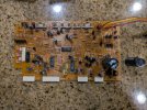
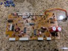
Let's end this post with some caps. I had the parts to recap the control board, and some of the VFD board:

PXL_20250214_003214734.jpgPXL_20250214_011002394.jpgPXL_20250214_010947729.MP.jpg

See the big caps in the lower right? Those are for the suck face motor circuit. When I replaced these, the speed and power on the suck face rose dramatically, to where it easily sucks in and recoils very quickly. Feels exactly how it should.


PXL_20250218_160439778.jpg

No board left behind! Even these little boards have a few caps, and they need replacement just like the main board. This board was tough to reach; the entire suck face had to be dismantled, then the metal frame attached to the 'sucker' that houses the tape counter and VFD has to come apart too.

Next post, the main board will be done, and I'll have better pictures of a summary of all the work done... It's a lot.

 
Last edited:
Let's continue on the KX-102 Restore.
Now, it's been taking me a lot longer to do this restore than I thought, and it's not because I've been working hard on it. Rather, the unit has been apart collecting dust and I've been just waiting on all the parts to show up that I ordered. I've had to buy a lot of parts from Germany, China, and the UK.
  • Purchased a special belt kit from Amazon that has exact fit suck face belt and cassette belts.
  • Purchased a replacement custom idler tire from Germany (take up reel slipped).
  • Bought special non-polar nichicon MUSE green capacitors for all bipolar caps from the UK.
  • Had to get some of the Nichicon Fine Golds from China. (Checked for correct capacitance and authenticity)
  • Ordered the usual standard value caps from Mouser.
  • Ordered a new micro switch for the suck face.
So, it's taken a long time and still some of the caps are in transit. I'm throwing a ton of parts at this thing, hoping to see the creaks, squeaks, and little issues disappear.

But, I really want the suck face to work on this deck, and I decided to purchase a belt kit that included the right thickness and diameter of belt. My problem with the suck face was that it made an abnormal howling noise and sometimes it was too weak to suck in or recoil back when powered down. The noise alone was enough to make me disable it. But, I decided to do a full rebuild of it and took it apart again and replaced my generic belt with a custom part:

View attachment 3432252View attachment 3432253

As you can see, the new belt is a perfect fit, and has good stretchiness to it. I used this Amazon kit sold by Bob's Vintage Audio Parts:

Anyways, I put some grease around the cam/planet gears to hopefully stop the noise, and reassembled the mechanism... unfortunately, I did what many others have done, I broke the micro switch:

View attachment 3432251

This switch is tiny, measuring only 12mm long. One of the poles broke off, and I wasn't even being that rough with it. I was gutted initially, because I had already read of folks having a difficult time sourcing a replacement. I did find one that worked ok, it was the OMRON D2HW-C221H. It is available from Mouser.

View attachment 3432250

It's a good bit bigger than the original... maybe 20% longer, and it's 5.3mm thick instead of the 3mm of the original. Now. It will not fit in between the cam and the assembly unless you Dremel off the peg facing the side of the cam and also shorten the metal arm to be flush with the edge of the switch case. Finally, the screw hole is much too big, but you can jam the entire screw head in the hole tightly, and then I made a little metal stabilizer that screws to the case which I attached onto the other peg I didn't have to Dremel. This stabilized the switch very well. I don't have any photos of this... can't really take any to show the process due to the size. In this photo, I had tried to use epoxy to hold it in place, of course it didn't work reliably... I am showing the metal addon I made in the video down below.

View attachment 3432249

Anyways, you can see how it fits... barely. With the screw head jammed in the switch's hole and screwed halfway through, and the epoxy added, it doesn't scrap or cause any undesired effect. I added the metal piece instead of the epoxy in the video below. Pardon the rotten soldering job on those wires... The wiring on the switch is different from the original, so I had to do some wire swapping a lot to get it right. I made it neat in the end. I think overall, you can't really find a replacement switch for this mechanism, but if you don't mind doing something that's a little unorthodox, this is a reliable fix that borderlines on Jerry rigging. So, with this, the suck face is operational and quiet... but is still weak.

Let's end this post with some caps. I had the parts to recap the control board, and some of the VFD board:

View attachment 3432281View attachment 3432282View attachment 3432283

See the big caps in the lower right? Those are for the suck face motor circuit. When I replaced these, the speed and power on the suck face rose dramatically, to where it easily sucks in and recoils very quickly. Feels exactly how it should. Here's a video:


View attachment 3432280

No board left behind! Even these little boards have a few caps, and they need replacement just like the main board. This board was tough to reach; the entire suck face had to be dismantled, then the metal frame attached to the 'sucker' that houses the tape counter and VFD has to come apart too.

Next post, the main board will be done, and I'll have better pictures of a summary of all the work done... It's a lot.
Very nice work replacing the switch! Just wait until you get to the RX103 suckface. That one is going to be a project! There's so much stuff around it you have to do a major disassembly just to get to it.
 
Very nice work replacing the switch! Just wait until you get to the RX103 suckface. That one is going to be a project! There's so much stuff around it you have to do a major disassembly just to get to it.

Just had a peek in my RX and yeah, you are right... and I'm dreading it. Replacing caps is easy compared to working with the suck face which certainly isn't. Funny enough, the RX came with a work order receipt in the box from an indie hifi shop where a technician had serviced just the suck face back in 2011. The KX also had an old work order from the same time... although the suck face wasn't mentioned. Incidentally, there were quite a few service receipts found, but all were for minor repairs... cracked solder joints, new cassette belt, lubed gear, etc.

My RX-103 has a smooth suck face with a failing micro switch; it moves in and out great but takes maybe 3 cam cycles before the micro switch actually triggers and the face stops... bummer.
 
I have the RX-102 got it from Goodwill. I recapped probably 50% of the unit and serviced the suck face mech. There is a how to video on You tube. I too love the looks at night when its lit up. It just sitting on the shelf at the moment. I'm enjoying my restored AU-719.
 
Let's continue on the KX-102 Restore.
Now, it's been taking me a lot longer to do this restore than I thought, and it's not because I've been working hard on it. Rather, the unit has been apart collecting dust and I've been just waiting on all the parts to show up that I ordered. I've had to buy a lot of parts from Germany, China, and the UK.
  • Purchased a special belt kit from Amazon that has exact fit suck face belt and cassette belts.
  • Purchased a replacement custom idler tire from Germany (take up reel slipped).
  • Bought special non-polar nichicon MUSE green capacitors for all bipolar caps from the UK.
  • Had to get some of the Nichicon Fine Golds from China. (Checked for correct capacitance and authenticity)
  • Ordered the usual standard value caps from Mouser.
  • Ordered a new micro switch for the suck face.
So, it's taken a long time and still some of the caps are in transit. I'm throwing a ton of parts at this thing, hoping to see the creaks, squeaks, and little issues disappear.

But, I really want the suck face to work on this deck, and I decided to purchase a belt kit that included the right thickness and diameter of belt. My problem with the suck face was that it made an abnormal howling noise and sometimes it was too weak to suck in or recoil back when powered down. The noise alone was enough to make me disable it. But, I decided to do a full rebuild of it and took it apart again and replaced my generic belt with a custom part:

View attachment 3432252View attachment 3432253

As you can see, the new belt is a perfect fit, and has good stretchiness to it. I used this Amazon kit sold by Bob's Vintage Audio Parts:

Anyways, I put some grease around the cam/planet gears to hopefully stop the noise, and reassembled the mechanism... unfortunately, I did what many others have done, I broke the micro switch:

View attachment 3432251

This switch is tiny, measuring only 12mm long. One of the poles broke off, and I wasn't even being that rough with it. I was gutted initially, because I had already read of folks having a difficult time sourcing a replacement. I did find one that worked ok, it was the OMRON D2HW-C221H. It is available from Mouser.

View attachment 3432250

It's a good bit bigger than the original... maybe 20% longer, and it's 5.3mm thick instead of the 3mm of the original. Now. It will not fit in between the cam and the assembly unless you Dremel off the peg facing the side of the cam and also shorten the metal arm to be flush with the edge of the switch case. Finally, the screw hole is much too big, but you can jam the entire screw head in the hole tightly, and then I made a little metal stabilizer that screws to the case which I attached onto the other peg I didn't have to Dremel. This stabilized the switch very well. I don't have any photos of this... can't really take any to show the process due to the size. In this photo, I had tried to use epoxy to hold it in place, of course it didn't work reliably... I am showing the metal addon I made in the video down below.

View attachment 3432249

Anyways, you can see how it fits... barely. With the screw head jammed in the switch's hole and screwed halfway through, and the epoxy added, it doesn't scrap or cause any undesired effect. I added the metal piece instead of the epoxy in the video below. Pardon the rotten soldering job on those wires... The wiring on the switch is different from the original, so I had to do some wire swapping a lot to get it right. I made it neat in the end. I think overall, you can't really find a replacement switch for this mechanism, but if you don't mind doing something that's a little unorthodox, this is a reliable fix that borderlines on Jerry rigging. So, with this, the suck face is operational and quiet... but is still weak.

Let's end this post with some caps. I had the parts to recap the control board, and some of the VFD board:

View attachment 3432281View attachment 3432282View attachment 3432283

See the big caps in the lower right? Those are for the suck face motor circuit. When I replaced these, the speed and power on the suck face rose dramatically, to where it easily sucks in and recoils very quickly. Feels exactly how it should. Here's a video:


View attachment 3432280

No board left behind! Even these little boards have a few caps, and they need replacement just like the main board. This board was tough to reach; the entire suck face had to be dismantled, then the metal frame attached to the 'sucker' that houses the tape counter and VFD has to come apart too.

Next post, the main board will be done, and I'll have better pictures of a summary of all the work done... It's a lot.
Jeez, that motor and gear noise is something...
 
Back
Top Bottom