• The move to the new server is done. There are some software and database maintenance updates in process. This has us passing the hat around to help out. We appreciate any donations. Seriously, even a dollar helps. The payment page may be found here - https://www.audiokarma.org/support.html

M-45 Recap and Service

WannaBeHiFi

Active Member
Hey y'all. I've been carrying on about recapping my M-45 for a while now. This evening Soundscape inspired me to quit talking about it and start doing it.
Disclaimer:
Once upon a time a much younger version of myself got an AS in electronics. I learned the basics, but I remember the math was a bitch. Then life happened and I didn't really use much of that education.
But I have no practical experience that would prepare me for such an undertaking. I have an old circuit board I can use to work on soldering skills.

I bought this specimen on Craigslist from a gentleman several years ago. He asked $300. After looking it over and hearing the background I didn't argue about the price. He bought it new in the '80's. It was his main power amp for about 15 years where it was housed in a clean cabinet with filtered circulation. It was replaced during an upgrade to McIntosh monoblocks. I didn't get to hear it, but this guy had some ****. One of those >10K turntables, 15k speakers. WTF. The M-45 was sent to live in a closet for 10+ years. Then I acquired it and kept it on the sidelines for a few years till my A-700 died. I've been using it now for 3-4 years.

Condition: Functionally, near as I can tell, there is nothing wrong with this amplifier. BUT, the electrolytics are near double their recommended life span. I suspect there has been some minor sonic degradation, but eventually something will fail. I figure that it's better to service it now, than to keep running it till the wheels fall off. That and I am curious to hear if returning it to its former glory will have an effect on sound quality. I'm guessing that's a function of how badly the caps have degraded. Generally, I'm not inclined to swap out equipment, I've got vehicles I probably WILL drive till the wheels fall off. If I can restore this M-45 to its former glory, I may not need another amp.

If I can pull this off, I have a dead C65 we might have a go at. But it's in much worse condition. I may be better off looking for a worthy C-85.

Initial inspection:
 

Attachments

  • IMG_5972.jpg
    IMG_5972.jpg
    162.9 KB · Views: 53
  • IMG_5973.jpg
    IMG_5973.jpg
    152.7 KB · Views: 51
  • IMG_5974.jpg
    IMG_5974.jpg
    82 KB · Views: 49
  • IMG_5975.jpg
    IMG_5975.jpg
    122.8 KB · Views: 48
  • IMG_5976.jpg
    IMG_5976.jpg
    103 KB · Views: 47
  • IMG_5977.jpg
    IMG_5977.jpg
    138.2 KB · Views: 47
  • IMG_5978.jpg
    IMG_5978.jpg
    113 KB · Views: 49
  • IMG_5980.jpg
    IMG_5980.jpg
    67.5 KB · Views: 51
  • IMG_5981.jpg
    IMG_5981.jpg
    104.6 KB · Views: 55
Register to hide this ad
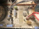
Sorry 'bout the dust. I just took opened it up this evening. Tomorrow, I'll take it out to the garage and blow the dust and spiders out of it.
 
It doesn't look too bad as far as glue goes.

Is that the bad glue?
It looks like the browning is more heat related than corrosion. I'm not seeing the green crusty corrosion that damaged multiple components in my A-700 or other glue damage pics posted to forum. The puddle that touches the resistor lying flat looks dark due to heat, because it's not touching the leads. It's harder to tell what's going on with the standing resistor, it's waste deep in goo.

Though I'm fired up to get started, I'm not in a hurry to finish. It will take as long as it takes. Hell, it took me over three years to restore that old motorcycle. I had no idea what I was doing when I started. Britbike Forum provided valuable advice and kept me from critical mistakes.

* I have the M-45 service manual with two schematics. The updated version shows the signal path with reference voltages throughout the circuit. I'm trying to figure out how to print parts of the schematic and tape together to have larger version that's easier to see, make notes on, and such. Low ink's got that on hold.
* Soldering tools are adequate, though I did invest in a good solder sucker.
* I've got a fair digital MM, and I invested in upgraded probes with clamp on tips.
* I put together one of those component tester kits.

The goal is careful, logical, methodical. No shotguns.

How should I go about this? Where to start?

Please and Thank You
 
Is that the bad glue?
Yeah. There's not alot of it though. The only part I see that looks concerning is the upright green resistor in the last photo.
IMO, the best way to re-cap is marking the top of the old caps with a marker. Mark a notch on the caps facing the front of the unit.
I would start by removing the big green caps with the dreaded glue around them. 1000uF, 80V. Now you have room to remove the glue and work that crucial signal path area better.
It's tempting to remove the glue with a screwdriver, don't. People use different things like chopsticks, wood shims, un-sharpened pencils, etc. I soften the glue with IPA (rubbing alocohol, don't pour your beer on it :biggrin: ). Some folks use acetone instead but they warn about getting it on other components, acetone will devour the yellow poly caps. Let's just not use acetone on our first job, lol. I'm generous with IPA. I dip paint brushes in it and clean boards with it. Warning about IPA though:
1. It will remove the marker notches on the caps
2. It will smear heat sink compound around.

I'll take a year on my threads sometimes. Life gets in the way, cars break down,etc. Just a hobby for me. We'll be around if needed. Hopefully other members chime in too.


This evening Soundscape inspired me to quit talking about it and start doing it.
:whip:
Have fun, it's really rewarding unless it blows up o_O
 
The goal is careful, logical, methodical. No shotguns.
So we're just replacing *electrolytic* caps right? Is that the main plan? (Aside from glue damaged parts, if any)
Edit: asking cuz many of us replace the trim pots and sometimes find a center display bulb is dead
 
So we're just replacing *electrolytic* caps right? Is that the main plan? (Aside from glue damaged parts, if any)
Edit: asking cuz many of us replace the trim pots and sometimes find a center display bulb is dead

No. It's 40 years old, is a good specimen, I like the sound it makes. I'd like to hang on to it. Replacing the expired caps is a major motivating factor, but if I'm going in, I want to perform a full service. Whatever it needs to reasonably restore to original spec. If possible, I don't want to change the voicing. I rather like the Natural Sound.

. I soften the glue with IPA (rubbing alocohol, don't pour your beer on it :biggrin: ). Some folks use acetone instead but they warn about getting it on other components, acetone will devour the yellow poly caps.

Well, one of my other interest, rabbit holes, is resurrecting or restoring vintage motorcycles. Go at fasteners that have sat around for 40 years with brute force, and you will pay the price. But with a good penetrant, small wire brushes, some patience, maybe a little heat, they will come off. ;)

So, I can relate to your advice to take a kinder gentler more empathetic approach.

First, I must take issue with your use of acronyms. I wholeheartedly reject the use of IPA in reference to isopropyl alcohol! That's just silly. Everyone and their brother knows that IPA stands for India Pale Ale. And if they don't, their probably Baptist.

Back to the question at hand, what about grain alcohol? Everclear. It's a little more potent than isopropyl, but a long way from acetone, and more fun than either! :beerchug:
 
IMO, the best way to re-cap is marking the top of the old caps with a marker. Mark a notch on the caps facing the front of the unit.

My understanding is the mark is a reference to the original orientation on the board. Apparently, a fair number of circuit boards back in the day had incorrect polarity markings.
 
My understanding is the mark is a reference to the original orientation on the board. Apparently, a fair number of circuit boards back in the day had incorrect polarity markings.
Yeah. Seems like there's always one or two polarity issues/board error. The mark also tells ya what has been replaced cuz I don't mark the new ones installed.
 
It's 40 years old, is a good specimen, I like the sound it makes. I'd like to hang on to it.
Yeah seems in good shape, gently used etc. I can tell when prior owners used the Class A button all the time :thumbsdown:. That M-45 looks like a good buy.
How should I go about this? Where to start?
Though we discussed this already, wanted to add some particulars. Recommend some board support underneath where the big green caps were to counter the sag & flex while poking at the glue. Odds are it won't break either way, I'm just fussy.

Remove the 2 small black plastic brackets on both sides of the front face panel. They often break if you don't remove them from all the chassis flip flopping. They look like a Japanese tongue depresser. :p

I place a cardboard flap underneath the pieces I work on. Makes spinning them easy, reduces scratches, absorbs excess fluids, & good for writing quick notes on.

IMO it's better to work with the transformer side down due to the weight. It will be on its side alot and that's what breaks the tongue depressers I was bitching about. :blah:

I'd rather not do solder work after drinking coffee. Jittery caffeinated hands cause errors. My best work is in the evening after a couple brews honestly. Getting too snookered? I turn off the iron and clean pots/flux, shop for parts,etc.

Esoteric Redneckisms
 
Last edited:
Take many many many good clean "before" photos, very methodically, of the entire amp, including the trace sides of boards, after cleaning the dust out and before doing any work. You will be glad to have the reference later.

One cap etc at a time, very methodically. Observe the actual polarity before touching the cap, each and every time. Compare to the board markings and and schematic and make notes if there are any discrepancies. Since it is an "un-disturbed" amp the original part orientation always wins the argument. Yamaha is notorious for getting the board markings and schematic wrong on some caps.

I am a proponent of using chopsticks for removing the glue once you get it softened with the liquid of your choice. The blunt end cut to a chisel tip, the pointy end sharpened in a pencil sharpener.

Now I will get out of the way and enjoy reading the thread.

:beerchug:,
James
 
Hey Y'all

C127, 128
Nichicon 1000uF, 80V with note UKJ. This is what I've found - the different series are confusing. Is this a worthy replacement?
Mouser UKW2A102MHD

I brushed and blew the cosmic debris and alien creatures from the amplifier guts. Its eagerly awaiting a photo shoot.

My soldering skills suck. I've got an ugly practice board to prove it. Workin' on it.
I've been assembling a collection of DEVICES with which to ATTACK the offending goo.
I'll give them a try if I can't get that stuff off with my pocketknife.

Starting a parts list.
Original state pictures next......
 
My soldering skills suck. I've got an ugly practice board to prove it.
Ooh can't wait to see the tragedy. I used to practice on old Sony pieces. IMO if a guy can de-solder and re-install a small transistor without damaging a trace he's qualified, lol.
Heat the component lead, not the board. 3 second cook time max. In and out quick like a robbery. Good solders look shiny, bad ones look dull. Massive blobs don't make them any stronger.
 
Last edited:
Back
Top Bottom