• The move to the new server is done. There are some software and database maintenance updates in process. This has us passing the hat around to help out. We appreciate any donations. Seriously, even a dollar helps. The payment page may be found here - https://www.audiokarma.org/support.html

M-45 Recap and Service

Hey Y'all

I hope you XY's are letting y'all's face grow long in celebration of Movember. I got a head start in October.

Capacitors 127,128: What is their purpose in the circuit?

I've been looking at the schematic, trying to remember things long forgotten. So, since those big ol honkin caps appear to be between the active amp circuit and ground, which is shared with the input, are those the caps that block DC from the inputs? Or am I off in the weeds?

Please and thank you.
 
Better get a weed whacker..:biggrin:
They are for smoothing and voltage reserve for the power amplifiers voltage amplifier rails.

Ok. Why does e see the + of one cap and the - of the other?

I took my bowie knife out last night and went at the alien goo. Considerable progress was made. :)
 
Why does e see the + of one cap and the - of the other?
One for the positive (+) 60vdc rail and one for the negative (-) 60vdc rail. Both referenced to circuit ground (E).
 
Last edited:
Hey y'all

Well, my Wifes stuff still remains, but she's workin' on it. So progress is being made.

Not to be deterred I made some space and proceeded to yank C127,128 outta that sucker.
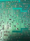
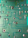
The pictures tell the tale. I whittled the DSBG with a bowie knife. Looks to me like I need to pull the flame resistors and a couple jumpers in order to clean corrosion or replace.

Using my MM, the 1000uF caps tested at 650 and 660uF.
 

Attachments

  • IMG_6005.jpg
    IMG_6005.jpg
    107.2 KB · Views: 16
  • IMG_6017.jpg
    IMG_6017.jpg
    146.7 KB · Views: 14
  • IMG_6014.jpg
    IMG_6014.jpg
    97.9 KB · Views: 15
  • IMG_6013.jpg
    IMG_6013.jpg
    83.2 KB · Views: 15
  • IMG_6012.jpg
    IMG_6012.jpg
    79.7 KB · Views: 15
  • IMG_6011.jpg
    IMG_6011.jpg
    117.5 KB · Views: 15
  • IMG_6010.jpg
    IMG_6010.jpg
    110.1 KB · Views: 16
  • IMG_6009.jpg
    IMG_6009.jpg
    116.2 KB · Views: 15
  • IMG_6008.jpg
    IMG_6008.jpg
    128 KB · Views: 15
Hmm, Interesting turn of events. I've entered into negotiation for a dead M-65 listed on CL. The unit won't come out of protection. The seller claims his repair guy declared a hard short in the power supply. That may be, but pictures provided on the listing clearly show the two big filter caps are missing with a few damaged components nearby. Somebody has been in there messing around. I've got a working Onkyo amp and some Bose 501's I've offered for trade. If we can come to terms, I might have another unit to use to further my education and possibly repair for use or resale.
 
Hey y'all

Well, my Wifes stuff still remains, but she's workin' on it. So progress is being made.

Not to be deterred I made some space and proceeded to yank C127,128 outta that sucker.
The pictures tell the tale. I whittled the DSBG with a bowie knife. Looks to me like I need to pull the flame resistors and a couple jumpers in order to clean corrosion or replace.

Using my MM, the 1000uF caps tested at 650 and 660uF.
Nice progress. I dip my toothbrush in IPA to clean the residuals.
 
Hmm, Interesting turn of events. I've entered into negotiation for a dead M-65 listed on CL. The unit won't come out of protection. The seller claims his repair guy declared a hard short in the power supply. That may be, but pictures provided on the listing clearly show the two big filter caps are missing with a few damaged components nearby. Somebody has been in there messing around. I've got a working Onkyo amp and some Bose 501's I've offered for trade. If we can come to terms, I might have another unit to use to further my education and
If it's cheap I'd buy it and put it in a dusty corner. I understand the Yamalust. Let's focus on the M-45 as it is the ultimate learner piece.
 
Last edited:
Nice progress. I dip my toothbrush in IPA to clean the residuals.

Thanks, haven't destroyed anything yet. To each their own. I'd rather sip the IPA while cleaning residuals.

M-65: The guy's asking $200, which is silly for a dead amp. If I can trade unused stuff for it great! Should I acquire, it deserves better than a dusty corner. I'm thinkin' perhaps fix it, sell it, and use the proceeds for a good C-85. There are too many if's to fret over it.

M-45: The resistor that was waist deep in goo needs to be removed, corrosion addressed or replace. I'll pull the jumpers for clean up. There is glue under them and in the holes that I can't get to. There is a red cap between the two flame resistant resistors that looks like it needs some love. I'll pull those tonight.

My wife has been called into babysitting duty this week which means I'll have lots of time in the evenings to work on the amp.
 
Well forum I have a problem.
I removed R143 the 4.7 1/4W Flame resistant resistor. Corrosion was minor. I cleaned up the leads with sandpaper. The resistor test at 4.79. I recon I'll keep it.
I removed C149 the 470pF 100V Polypropylene film cap. Cleaned it up. The cap test at 460pF. I recon I'll keep it as well.
I removed J568 and cleaned it.

When I was cleaning up. Sigh. I boogered up the board where J568 connects.

What do I do about this.
 

Attachments

  • IMG_6027.jpg
    IMG_6027.jpg
    126.1 KB · Views: 16
  • PCB Diagram.jpg
    PCB Diagram.jpg
    73.2 KB · Views: 16
It seems I lifted about 3/4 of the pad. I carefully rolled the flap back into position. I then checked continuity between the pad and the other components on that trace. I'm not sure what to do about the end of the trace that lifted. Tack it down with an adhesive? Reinstall the jumper as is?
 

Attachments

  • IMG_6027.jpg
    IMG_6027.jpg
    126.1 KB · Views: 5
  • IMG_6028.jpg
    IMG_6028.jpg
    107.3 KB · Views: 5
I wanna see if anyone would agree with how I'd do it...:dunno:

I would coat a 22AWG copper wire with flux and tin it with solder. Longer than needed. Then feed it through the lifted trace from the green side of the board toward the good side & solder down the good side first. Then I'd pull it tight and bend the excess jumper over the lifted pad so it holds it down and then solder it. Then cut off the excess wire. I think it would hold as is without glue.
 
Have some flux? Plan B redneckism: Cut off the pad with a razor and etch off the green mask with a small screwdriver to expose the copper of the trace. Solder jumper over exposed trace. Flux is key to minimize heat time or the trace will keep peeling back. Prep clean with IPA. Flux also cleans in addition to bonding quicker.

There's you tube videos out there too
 
Last edited:
Back
Top Bottom