FireGuruMN
Active Member
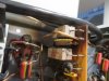
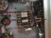
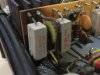
I have embarked on a quest to get all of my old audio equipment (Heath-kit, Carver, Phase Linear, Sansui, Marantz, Luxman since name dropping seems to be popular here  ) in working order. I will then in a big rack with a patch bay to select which device I will listen to on a given day. But I have never had any McIntosh so I picked up a MA5100 which seemed like the appropriate vintage to fill in the 1960's. The display circuit on the amp was blown out because they had the wrong bulbs. I fixed that first. Ya GOTTA have a working display on a Mac. The amplifier put out relatively good sound but the bass was mushy. So I ordered up a set of Sprague Atoms and soldered them in the preamp and driver boards and what ever that circuit by the balance knob is (sorry for the display of ignorance). I am relatively sure one even had a broken lead on the right driver board. After doing the last cap on the preamp board I powered it up. Now I have a buzzing in the left channel. Like a wire shield fell off or something. I can't see anything obvious. I did have a problem with popping in the left channel but that went away when I took the front metal piece off. I think it was a pinched wire. Or maybe it was a short that I lengthened and that created the problem. The buzz goes away when you hold the phase switch in the exact middle which essentially disconnects the left preamp channel from the driver board. Interestingly the buzz also goes away when you turn the treble all the way up or down. The buzz is not affected by the input selector or really anything on the front panel. It gets louder and softer with the volume control. Where should I continue my investigation?
Interestingly has anyone ever noticed that the polarity on the C20 capacitor is backwards on the circuit diagram of the service manual? I checked the voltage on the circuit board and installed it to match. That keeps the beautiful symmetry of that boards design. Looking at pictures on like it seems like half are one way and half are the other. Maybe it is not enough voltage to cause smoke.
Just to declare everything: When trimming the leads off one capacitor the trimmed piece went flying away and I have never found it. Could it be lurking around in the amp causing this problem? I doubt it. It is probably lost on my workbench somewhere.
I don't know if it is normal or not but almost any wire on the preamp that I get close to will cause a buzzing in both channels.
Any encouragement and/or support will be appreciated.
) in working order. I will then in a big rack with a patch bay to select which device I will listen to on a given day. But I have never had any McIntosh so I picked up a MA5100 which seemed like the appropriate vintage to fill in the 1960's. The display circuit on the amp was blown out because they had the wrong bulbs. I fixed that first. Ya GOTTA have a working display on a Mac. The amplifier put out relatively good sound but the bass was mushy. So I ordered up a set of Sprague Atoms and soldered them in the preamp and driver boards and what ever that circuit by the balance knob is (sorry for the display of ignorance). I am relatively sure one even had a broken lead on the right driver board. After doing the last cap on the preamp board I powered it up. Now I have a buzzing in the left channel. Like a wire shield fell off or something. I can't see anything obvious. I did have a problem with popping in the left channel but that went away when I took the front metal piece off. I think it was a pinched wire. Or maybe it was a short that I lengthened and that created the problem. The buzz goes away when you hold the phase switch in the exact middle which essentially disconnects the left preamp channel from the driver board. Interestingly the buzz also goes away when you turn the treble all the way up or down. The buzz is not affected by the input selector or really anything on the front panel. It gets louder and softer with the volume control. Where should I continue my investigation? Interestingly has anyone ever noticed that the polarity on the C20 capacitor is backwards on the circuit diagram of the service manual? I checked the voltage on the circuit board and installed it to match. That keeps the beautiful symmetry of that boards design. Looking at pictures on like it seems like half are one way and half are the other. Maybe it is not enough voltage to cause smoke.
Just to declare everything: When trimming the leads off one capacitor the trimmed piece went flying away and I have never found it. Could it be lurking around in the amp causing this problem? I doubt it. It is probably lost on my workbench somewhere.
I don't know if it is normal or not but almost any wire on the preamp that I get close to will cause a buzzing in both channels.
Any encouragement and/or support will be appreciated.