• The move to the new server is done. There are some software and database maintenance updates in process. This has us passing the hat around to help out. We appreciate any donations. Seriously, even a dollar helps. The payment page may be found here - https://www.audiokarma.org/support.html

Maggie 9301 9302 differences

BrandXRC

BrandXRC
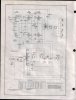
Does anyone know why the different feedback resistors between a 9301 and a 9302 chassis. The 9301 uses R109/R209 4700 ohm and R112/R212 2200 ohm. The 9302 uses R109/R209 2200 ohm and R112/R212 3900 ohm respectivly.
What sonic differences would it make. Which combo should I go with useing Edcor Trannys.
 

Attachments

Register to hide this ad
Thanks Battradio, But can you explain a bit why. I hate to do something and not know why...Could it be that they were for different speaker complements? One other thing on the 9302, how much should I increase the power supply filter caps, or should I stay with the 40,30,10?
 
Last edited:
Thanks Battradio, But can you explain a bit why. I hate to do something and not know why...Could it be that they were for different speaker complements? One other thing on the 9302, how much should I increase the power supply filter caps, or should I stay with the 40,30,10?

somewhere there's a thread by (I think) GordonW, and if memory serves:

first one, stay the same to keep the rectifier tube happy . . . 2nd one you can go higher with (100 - 200 MFD), and third one bump up to around 40 or 60 MFD. I also believe the first big power supply resistor needs to be upped to bring the overall voltages down to account for the tuner chassis not being connected . . .
 
Thanks Battradio, But can you explain a bit why. I hate to do something and not know why...Could it be that they were for different speaker complements? One other thing on the 9302, how much should I increase the power supply filter caps, or should I stay with the 40,30,10?

The amp was most stable and had the best frequincy responce with that resistor and that tap of the output transformer , with out using too much feedback .Stay with 40uf at the 5U4 , 100 to 470 uf after the choke is fine and and use a .1 uf by pass cap across it , 40uf or more for the front end .Use 220 to 470 uf across the cathode bias resistor for the 6BQ5's .

The 100Uf or larger after the choke , provides a B+ reserve for the output tubes
 
The amp was most stable and had the best frequincy responce with that resistor and that tap of the output transformer , with out using too much feedback .Stay with 40uf at the 5U4 , 100 to 470 uf after the choke is fine and and use a .1 uf by pass cap across it , 40uf or more for the front end .Use 220 to 470 uf across the cathode bias resistor for the 6BQ5's .

The 100Uf or larger after the choke , provides a B+ reserve for the output tubes

I like his answer better than mine :D
 
but both answers are needed in order to get a better grasp of the overall affect messing with cap values has on amp operation. IMO.
 
The different feedback resistor values probably had something to do with the speaker compliment in a particular unit. Magnavox "voiced" their amps to a particular speaker and cabinet combination for best results.

I found that mine sounded better by increasing the value of the feedback resistors to the highest ones listed on the schematic, producing the least amount of NFB. It gave me more gain and it sounded a lot more natural. With more feedback, the sound was flat with little gain. It may have been more "pure" by the numbers. but it sounded lousy. The lows were missing, the highs were missing, and the mids were just blah.
 
Thanks for the info guys. oldhifiguy is right, It did help me understand why I am doing this. I noticed most 450 and up voltage caps stop at about 100, is it OK to use two 100's for 200?
 
The different feedback resistor values probably had something to do with the speaker compliment in a particular unit. Magnavox "voiced" their amps to a particular speaker and cabinet combination for best results.

I found that mine sounded better by increasing the value of the feedback resistors to the highest ones listed on the schematic, producing the least amount of NFB. It gave me more gain and it sounded a lot more natural. With more feedback, the sound was flat with little gain. It may have been more "pure" by the numbers. but it sounded lousy. The lows were missing, the highs were missing, and the mids were just blah.


Hmm,
The schematic shows two different resistors in the circuit that change according to model type. R109-209 and R112-212. You have a 4700ohm/2200ohm combo or 2200/3900 combo.

How did you change yours? To 4700/3900?
 
Hmm,
The schematic shows two different resistors in the circuit that change according to model type. R109-209 and R112-212. You have a 4700ohm/2200ohm combo or 2200/3900 combo.

How did you change yours? To 4700/3900?

hm, didn't notice the second set. I think I changed R112/212 to 3900. The others are whatever they were originally. I seem to remember removing a 2200 ohm resistor in favor of the 3900 though. I may have to try changing the others just to see what happens.
 
The amp was most stable and had the best frequincy responce with that resistor and that tap of the output transformer , with out using too much feedback .Stay with 40uf at the 5U4 , 100 to 470 uf after the choke is fine and and use a .1 uf by pass cap across it , 40uf or more for the front end .Use 220 to 470 uf across the cathode bias resistor for the 6BQ5's .

The 100Uf or larger after the choke , provides a B+ reserve for the output tubes

OK-
To be clear, replace C2b at 30uf with 100uf up to 470uf and 450VDC. Now, when you say use a 0.1uf bypass cap across it, do you mean place another cap parallel to ground with the new 100-470uf?
 
hm, didn't notice the second set. I think I changed R112/212 to 3900. The others are whatever they were originally. I seem to remember removing a 2200 ohm resistor in favor of the 3900 though. I may have to try changing the others just to see what happens.

Which amp do you have- 9301 or 9302?

9301 calls for 4700/2200
9302 calls for 2200/3900

I obviously have the 9302.
 
Thanks Battradio...I used stock values for my AMP142's also. They were 30,30,10,10. Do you know which ones I should or should not up there?
 

Attachments

  • 142.jpg
    142.jpg
    78.9 KB · Views: 27
Thanks Battradio...I used stock values for my AMP142's also. They were 30,30,10,10. Do you know which ones I should or should not up there?

The first 30uf right after the two 5Y3's needs to stay the same , the second 30 can be 200 to 300 uf the first 10uf can be replaced by a 30 to 50 uf and the 10uf across the cathode resistor should be between 220 uf and 470 uf with a .47 uf cap acoss it .
 
Which amp do you have- 9301 or 9302?

I have two of them actually. The one I changed the resistors on is a 9304-20, the 9302 has whatever it came with. Schematic shows the same value parts, but I can definitely tell you the resistors were not the same values. The 9304 was virginal when I got it. The 9302 had been re-capped but the feedback resistors were/are original.

Cathode caps dont need to be 450. Most things used a 25-50v cap for that job, depending on the actual circuit voltage.
 
Thanks. My goof. I have 220uf, 35vdc now on Mark's excellent advice.

I am just wondering if changing the R109/209 from 2200 to a higher value would have the sonic benefits you found. Would going to 4700 make much of a difference?
 
Back
Top Bottom