• The move to the new server is done. There are some software and database maintenance updates in process. This has us passing the hat around to help out. We appreciate any donations. Seriously, even a dollar helps. The payment page may be found here - https://www.audiokarma.org/support.html

Maggie 9303: suddenly very low volume and distorted

I would like to take credit for installing the Edcors, but I can't. I knew someone locally who works on vacuum tubes and he seemed to know what he was doing (wish I did!). I may have even sent him an AK thread on the Edcor modifications. But he has left the area.

I'm not 100 percent sure of the model, but I think it's CXPP25-8K. It has 4, 8 and either 12 or 16 ohm taps.
 
Yeah, the power supply needs all new caps and resistors at least.

Post pics showing all the parts underneath. There may be more damage.

Did you install the Edcor OTs yourself? Has this had any previous electrical restoration?[/QUOTE}

Thanks, FlaCharlie, this Maggie was one I bought restored, without the Edcors--which someone locally installed. He also did other upgrades because he was concerned about some of the original work.

I can do only basic soldering, but I'm pretty sure I can replace a couple of transistors if that is indicated.

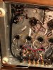
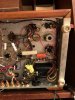
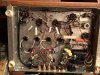
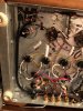
Here are pics of the underside:
 

Attachments

  • IMG_6226.jpeg
    IMG_6226.jpeg
    130.9 KB · Views: 31
  • IMG_6225.jpeg
    IMG_6225.jpeg
    132.7 KB · Views: 32
  • IMG_6227.jpeg
    IMG_6227.jpeg
    116.6 KB · Views: 32
Thanks, FlaCharlie, this Maggie was bought restored, without the Edcors--which someone locally installed. He also did other upgrades because he was concerned about some of the original work.

I can do only basic soldering, but I'm pretty sure I can replace a couple of resistors if that is indicated.

Here are pics of the underside:
 

Attachments

  • IMG_6227.jpeg
    IMG_6227.jpeg
    116.6 KB · Views: 16
  • IMG_6225.jpeg
    IMG_6225.jpeg
    132.7 KB · Views: 14
  • IMG_6226.jpeg
    IMG_6226.jpeg
    130.9 KB · Views: 15
didn't even notice the Edcors. Which ones? I posted a thread on here somewhere about specific HF tuning that mine wanted in order to really behave properly. Its a variant on Dave Gillespie's work on the 9300. He tuned it for both the original transformers and whatever the Dyna ST-35 iron is. I took that basic circuit and fiddled with it so my Edcors responded properly.

https://audiokarma.org/forums/index.php?threads/magnavox-9300-with-edcor-cxpp25-ms-8k-iron.754809/

Actually, I probably sent my repair guy that thread because it mentions the Edcor model that I think we used. Thanks!
 
Thanks, FlaCharlie, this Maggie was bought restored, without the Edcors--which someone locally installed. He also did other upgrades because he was concerned about some of the original work.

I can do only basic soldering, but I'm pretty sure I can replace a couple of resistors if that is indicated.

Here are pics of the underside:
I couldn't tell from your earlier pic but it looks like the can cap is probably original. I'd suggest replacing all the sections with individual caps mounted underneath on a terminal strip with new resistors too, of course. Just leave the original can in place for looks.

High quality brands rated for 10,000 hours at 105 degrees are pretty cheap and Digi-Key has a free shipping option.

http://www.audiokarma.org/forums/in...hipping-on-parts-orders.739513/#post-10018562

The question is, what caused that resistor to burn? They don't typically just fail from old age, it's usually because something in the amp is drawing too much current.

I can't tell but have the coupling caps been replaced? They should be checked to see if they are (electrically) leaky. If they are you will measure DC on the grids of the output tubes.
 
IMG_4858.jpg Thanks, FlaCharlie. I guess I need to buy a multimeter. I thought it had been completely recapped, at least during its stay in the shop.

Maybe I should start by replacing that one you said was fried under the can. I guess it is the one between the red and black wires. When I tapped it it cracked right down the middle. Would you know offhand its value? Maybe I can tell from the schematic.

As far as figuring out whether something is drawing too much current, that is out of my league, at least at this point. Thanks!
 
To do the "terminal strip" procedure you advise, where do you suggest starting? Would I need to remove the can? Where would I find such a strip? Thanks, everybody, for your help.
 
can can stay. I leave it there to plug the hole.

#4-40 x 1/4" screws are about right to mount the terminal strips. Need some of those, matching nuts, a terminal strip, and a drill to make it all go together. AES and most of the other vintage parts suppliers sell them. I think Mouser and Digikey do too, though I haven't bought a modern one. Mine are all cheap NOS ones found at hamfests and such.
 
View attachment 2088184 Would you know offhand its value? Maybe I can tell from the schematic.

Did the tech replace the output transformers but not the capacitors?? That would be a little surprising...

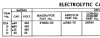
The values of the capacitors in the the can can be found on the schematic, just to the right of the 5U4 rectifier tube at the bottom. On my version of the schematic it's 40uF, 30uF and 10uF, all listed under C2 (C2 being the can those are all inside). These need to be 450v (or higher). Or you can look on the outside of the can, often it’s printed right onto the can.

As I understand it, it is wise to keep the first cap (the 40uF) the same value so as to not stress the rectifier, but the others can be somewhat higher capacitance, and there is some benefit to doing so.

Worth mentioning here is that when you start messing with power supply capacitors you are dealing with potentially lethal voltages. Be sure to take all necessary precautions.
 
Last edited:
Thanks, Kirk. Most of the visible caps look pretty new, but I don't know what's under the can. Not sure yet how to bypass the can but will cross that bridge when I get there.

I'm a little worried about safety, since I have a kidney transplant. So I may see if a local music store that works on guitar amps can help with this. At some point I did solder leads from the preamp into the underchassis, with the expert help of another AK member, and had no safety issues. Seems like goggles are the most important precaution?

About how many uF above spec would you go with those caps? Would it change the sound (which I really love--I'm going into withdrawal!)?

Your Lincoln quote is hysterical! Thanks for all this help.
 
You can also have a can made up by Hayseed Hamfest if you are not comfortable drilling and mounting caps on tag strips (make sure you get ones that ground one of the tags via the mounting tag) I've done it both ways on the handful of Magnavoxes I have redone. They run around $40 including shipping yeh I know a little pricey but a easier job than installing separate caps FWIW
 
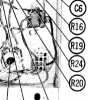
Thanks, Mark, Hayseed sounds like a good way to go. My hands are a bit shaky for soldering anything too demanding. Meanwhile, I may just start with that one clearly fried resistor directly beneath the can, which from the diagram and value chart posted by FlaCharlie seems to be R 24 (10K) (see detail below). Does that make sense? Am I looking at the diagram from the right angle?

upload_2021-1-8_16-16-38.png
 
Personally I would want to determine if the cap/caps aren't shorted first and if they are ok then the resistor. R 24 is the one that fried. Schematic is rotated different than your pic. Do you have a tester for caps?
 
There was several discussions about cap value. I just got a hayseed can with all 47uf 450v caps in it based on different suggestions by members. The original DG mod schematic showed 40 30 10 30
 
Thanks, Mark. I don't have a cap tester, but I plan to take the leap. Replacing the can with the Hayseed 47uf/450v seems like the route to go if I can figure out how to remove it.
 
Thanks, Kirk. Most of the visible caps look pretty new, but I don't know what's under the can. Not sure yet how to bypass the can but will cross that bridge when I get there.

I'm a little worried about safety, since I have a kidney transplant. So I may see if a local music store that works on guitar amps can help with this. At some point I did solder leads from the preamp into the underchassis, with the expert help of another AK member, and had no safety issues. Seems like goggles are the most important precaution?

About how many uF above spec would you go with those caps? Would it change the sound (which I really love--I'm going into withdrawal!)?

I just followed the schematic posted by Dave Gillespie here. I can't say I have any way to compare before and after, but I love the result, and it's been my main amp for a couple of years now and I have, shall we say, a *few* other amps...
 
I just followed the schematic posted by Dave Gillespie here. I can't say I have any way to compare before and after, but I love the result, and it's been my main amp for a couple of years now and I have, shall we say, a *few* other amps...

I meant to thank you, Kirk, for the Dave Gillespie link, which is way over my head but I seem to pick up a little more with every tweak or repair I make.
 
To do the "terminal strip" procedure you advise, where do you suggest starting? Would I need to remove the can? Where would I find such a strip? Thanks, everybody, for your help.
Your earlier pic of the can was pretty blurry and it didn't show the side with the values on it. So you should check to see if it is indeed the original.

The original has four sections with the low voltage one being the cathode bypass cap.

Maggie Can .png

If you leave the original in place make sure you totally disconnect it, don't just wire replacement caps in parallel with the originals. One reason I prefer to go with individual caps is that they are much cheaper and, unless you get a custom can from Hayseed, their specs are much better than typical replacement cans.

The other reason is that, although the original can uses a "twist lock" mount, they are typically also soldered to the chassis. So removing them requires that the big patch of solder be melted and since it's right on the chassis it takes a pretty powerful soldering iron to melt it because most of the heat sinks into the surrounding chassis.

So it might be easier to either drill a hole or find another way to mount a terminal strip. Looking at your pics, there is a screw protruding through the chassis that was used to mount the power switch. You could easily mount a terminal strip to that screw with just a lock washer and a nut. If the diameter of the screw is too large you could add a washer to the top and replace it with a thinner screw that fits through the hole in the terminal strip.

I'm sure Digi-Key also sells traditional terminal strips, like the one the orange cap is mounted to.

There is still the question of what caused the resistor to burn up. Something is drawing too much current. Could be a bad coupling cap. Are you sure those white caps are new? I can't really tell what they are from the pics.

The original can uses symbols (square, triangle, semi-circle) to identify the sections. See above. Which sections were connected by the burned resistor?

 
Your earlier pic of the can was pretty blurry and it didn't show the side with the values on it. So you should check to see if it is indeed the original.

The original has four sections with the low voltage one being the cathode bypass cap.

View attachment 2092946

If you leave the original in place make sure you totally disconnect it, don't just wire replacement caps in parallel with the originals. One reason I prefer to go with individual caps is that they are much cheaper and, unless you get a custom can from Hayseed, their specs are much better than typical replacement cans.

The other reason is that, although the original can uses a "twist lock" mount, they are typically also soldered to the chassis. So removing them requires that the big patch of solder be melted and since it's right on the chassis it takes a pretty powerful soldering iron to melt it because most of the heat sinks into the surrounding chassis.

So it might be easier to either drill a hole or find another way to mount a terminal strip. Looking at your pics, there is a screw protruding through the chassis that was used to mount the power switch. You could easily mount a terminal strip to that screw with just a lock washer and a nut. If the diameter of the screw is too large you could add a washer to the top and replace it with a thinner screw that fits through the hole in the terminal strip.

I'm sure Digi-Key also sells traditional terminal strips, like the one the orange cap is mounted to.

There is still the question of what caused the resistor to burn up. Something is drawing too much current. Could be a bad coupling cap. Are you sure those white caps are new? I can't really tell what they are from the pics.

The original can uses symbols (square, triangle, semi-circle) to identify the sections. See above. Which sections were connected by the burned resistor?

Thanks, FlaCharlie, for all this great advice! The tech, a seemingly smart guy who mostly repaired guitar amps for a local music store, apparently took a NASA job somewhere and I can't find him. But as I recall he said he had replaced most if not all of the caps and the can (see photo below), and it does look new. Would it have gone bad this soon? I guess it's been a year or so.

Would something like this this work for the can?

https://www.angela.com/50uf50uf500vdcclampmountelectrolyticcapacitor.aspx

He also, at my request, installed the Edcors and I must say the unit was sounding 1,000 percent better, especially in the bass department, until a few days ago. It occurs to me I might have accidentally turned up it way too loud for a second--I never need too much volume or power.

The other thing is that, as I mentioned, I replaced the rectifier tube, which went out maybe two or three months ago. Could that be a problem?

Very grateful for all your incredible help with this.
 

Attachments

  • IMG_6250.jpg
    IMG_6250.jpg
    72.5 KB · Views: 27
Last edited:
Back
Top Bottom