

You are using an out of date browser. It may not display this or other websites correctly.
You should upgrade or use an alternative browser.
You should upgrade or use an alternative browser.
Maggie 9303: suddenly very low volume and distorted
- Thread starter Moonwatcher
- Start date
-
- Tags
- 9300 9303 distortion magnavox volume

FlaCharlie
Super Member
Since the can was replaced I would assume it's good until proven otherwise. If it did go bad, the one you linked would only replace two of the four sections, so not really the way to go.Thanks, FlaCharlie, for all this great advice! The tech, a seemingly smart guy who mostly repaired guitar amps for a local music store, apparently took a NASA job somewhere and I can't find him. But as I recall he said he had replaced most if not all of the caps and the can (see photo below), and it does look new. Would it have gone bad this soon? I guess it's been a year or so.
Would something like this this work for the can?
https://www.angela.com/50uf50uf500vdcclampmountelectrolyticcapacitor.aspx
He also, at my request, installed the Edcors and I must say the unit was sounding 1,000 percent better, especially in the bass department, until a few days ago. It occurs to me I might have accidentally turned up it way too loud for a second--I never need too much volume or power.
The other thing is that, as I mentioned, I replaced the rectifier tube, which went out maybe two or three months ago. Could that be a problem?
Very grateful for all your incredible help with this.
One reason why I thought the can was original was that the resistors between the sections seem to be the original carbon comps. I suppose the tech may have re-used them if he didn't have any suitable new ones in stock. It's also possible that the burned one had been damaged previously.
At this point, I would replace the burned resistor (and any remaining original resistors in the power supply), bring the voltage up slowly using a variac and measure along the way in order to make sure that there isn't something that's drawing too much current.

Moonwatcher
Active Member
Thanks a million for this, FlaCharlie. My feeling, too, was to start with the obvious failed resistor (R24 on schematic).
I haven't done much tube work myself besides solder the various colored leads of that crazy preamp umbilical cable into the undercarriage of the amp, probably my most ambitious project so far, and it did work(!). So having done that, I feel like I could easily replace the resistor.
And I think I can get a variac locally at Harbor Freight (or wait for one from Amazon or eBay), but I'm not sure how I would do this:
"measure along the way in order to make sure that there isn't something that's drawing too much current."
I assume I would need a multimeter, which I can get at the same time as the variac, but I'm not sure at what points I should measure current, or what it should be.
Also, I think that resistor is supposed to be 10K, according to the schematic, but isn't there another value to consider, like watts? Sorry for my idiocy!
Safety is a bit of a concern. The amp has been unplugged for at least a week, and I understand about using just one hand to avoid cardiac arrest. But after surviving two kidney transplants and West Nile, I would hate for a glorified record player to finally pull the plug on me!
I did find out today that there is another music store repair guy in town who might be able to do this, though I'm sure he's mainly used to guitar amps.
I would very much like to take this on myself and maybe learn something along the way, as I do every time I get help from the kind folks here like you. But given my limited experience and understanding, do you think I should turn it over to him?
Thanks.
I haven't done much tube work myself besides solder the various colored leads of that crazy preamp umbilical cable into the undercarriage of the amp, probably my most ambitious project so far, and it did work(!). So having done that, I feel like I could easily replace the resistor.
And I think I can get a variac locally at Harbor Freight (or wait for one from Amazon or eBay), but I'm not sure how I would do this:
"measure along the way in order to make sure that there isn't something that's drawing too much current."
I assume I would need a multimeter, which I can get at the same time as the variac, but I'm not sure at what points I should measure current, or what it should be.
Also, I think that resistor is supposed to be 10K, according to the schematic, but isn't there another value to consider, like watts? Sorry for my idiocy!
Safety is a bit of a concern. The amp has been unplugged for at least a week, and I understand about using just one hand to avoid cardiac arrest. But after surviving two kidney transplants and West Nile, I would hate for a glorified record player to finally pull the plug on me!
I did find out today that there is another music store repair guy in town who might be able to do this, though I'm sure he's mainly used to guitar amps.
I would very much like to take this on myself and maybe learn something along the way, as I do every time I get help from the kind folks here like you. But given my limited experience and understanding, do you think I should turn it over to him?
Thanks.
Last edited:
FlaCharlie
Super Member
Can you do this yourself? Sure. The downside is that it does require some tools and only you can decide whether you'd rather spend some money on tools or pay someone else to do it. The tools will probably cost less unless you can find a tech who works cheap.Thanks a million for this, FlaCharlie. My feeling, too, was to start with the obvious failed resistor (R24 on schematic).
I haven't done much tube work myself besides solder the various colored leads of that crazy preamp umbilical cable into the undercarriage of the amp, probably my most ambitious project so far, and it did work(!). So having done that, I feel like I could easily replace the resistor.
And I think I can get a variac locally at Harbor Freight (or wait for one from Amazon or eBay), but I'm not sure how I would do this:
"measure along the way in order to make sure that there isn't something that's drawing too much current."
I assume I would need a multimeter, which I can get at the same time as the variac, but I'm not sure at what points I should measure current, or what it should be.
Also, I think that resistor is supposed to be 10K, according to the schematic, but isn't there another value to consider, like watts? Sorry for my idiocy!
Safety is a bit of a concern. The amp has been unplugged for at least a week, and I understand about using just one hand to avoid cardiac arrest. But after surviving two kidney transplants and West Nile, I would hate for a glorified record player to finally pull the plug on me!
I did find out today that there is another music store repair guy in town who might be able to do this, though I'm sure he's mainly used to guitar amps.
I would very much like to take this on myself and maybe learn something along the way, as I do every time I get help from the kind folks here like you. But given my limited experience and understanding, do you think I should turn it over to him?
Thanks.
But it's a slippery slope. Once you've spent some money on tools and your amp is fixed up you'll start looking at the tools and thinking that it's a shame that they're sitting there doing nothing. So you'll end up buying another tube amp . . . etc, etc.
Yes, you'll need a digital multimeter. I recently replaced my old Radio Shack meter that had gotten wonky with a Klein from Home Depot. Lots of choices and no need to get anything super expensive to get started.
You could save some money by building a DBT (dim bulb tester) instead of buying a variac. That's what I used at first. Do a search, they're cheap and easy to build. A piece of wood, a light socket, an extension cord and a selection of incandescent light bulbs.
In this situation, bringing the voltage up slowly is done to make sure that, if there is a problem, the new resistor doesn't just burn up immediately.
A voltage measurement will tell you if all is well.
If you look at the schematic you'll see that on one side of the resistor there is 325v and on the other side there's 300v. So the resistor is dropping 25v. If that part of the circuit is drawing excess current the voltage drop will be much higher and the resistor will get too hot and burn up.
According to the schematic, the resistor is rated at 1/2 watt. Resistors are "derated", meaning that their rating should be higher than the actual amount of power going through them. The current and the wattage that's actually being dissipated by the resistor can be determined with a calculator using Ohm's Law. Very basic algebra.
I won't go through the math step by step right now but there should be only about 2.5 mA of current which means the 10k resistor will be dissipating .062 watts and it's rated at .5w.
Safely draining voltage from charged caps is not difficult. I use a simple clip lead and a 100 ohm 10w resistor.
Moonwatcher
Active Member
Thanks, Charlie. I started down that slippery slope a few years ago when a screechy pair of Smaller Advents led me here.
So I've ordered a variac and multimeter, and found YouTube videos on draining caps.
I saw what you meant about the resistor dissipation. I ordered a 1.0 watt resistor. Would that extra wattage help protect it?
Where you say a voltage measurement will tell you all is well, are you referring to a measurement on the meter on the variac or a measurement somewhere on the amp with the multimeter? I'm sure this will make more sense when I have those in hand.
Thanks again for all your help with this.
So I've ordered a variac and multimeter, and found YouTube videos on draining caps.
I saw what you meant about the resistor dissipation. I ordered a 1.0 watt resistor. Would that extra wattage help protect it?
Where you say a voltage measurement will tell you all is well, are you referring to a measurement on the meter on the variac or a measurement somewhere on the amp with the multimeter? I'm sure this will make more sense when I have those in hand.
Thanks again for all your help with this.
FlaCharlie
Super Member
Well, it will take even more current to burn up a 1w than a 1/2w but even the smaller one is seriously de-rated (rated for 8x the current going through it). You could actually use a 1/4w there safely. The rule of thumb is to de-rate by a factor of 3. I usually try to go with 5 if I can.Thanks, Charlie. I started down that slippery slope a few years ago when a screechy pair of Smaller Advents led me here.
So I've ordered a variac and multimeter, and found YouTube videos on draining caps.
I saw what you meant about the resistor dissipation. I ordered a 1.0 watt resistor. Would that extra wattage help protect it?
Where you say a voltage measurement will tell you all is well, are you referring to a measurement on the meter on the variac or a measurement somewhere on the amp with the multimeter? I'm sure this will make more sense when I have those in hand.
Thanks again for all your help with this.
So while the resistor is less likely to burn, the downside is that the current being drawn can be even further out of spec before it goes up in smoke. Think of it like this . . . If an amp has a 2A fuse and it blows, sure you can put in a 10A or 20A fuse and it won't blow but it doesn't solve the problem and just makes it more likely that the amp ends up damaged more extensively.
So you really need to measure to make sure the circuit is operating correctly.
What you measure is the voltage drop across the resistor using your multimeter. The drop should be 25v or thereabouts. The more current, the bigger the drop. Ohm's Law can be used to determine the exact current.

resistors tend to be able to handle way beyond their ratings before they actually go totally open though. I've seen plenty of resistors that were absolutely incinerated that still had some resistance measurement even if it was nowhere close to what it should have been.
Moonwatcher
Active Member
Thanks, and as soon as I have the variac (due to arrive in a week or so) I'll check back. I've found YouTube videos and other sites on bringing up an amp with a variac. Meanwhile, is there any other testing I could or should do with my brand new multimeter without the amp's being powered up?
Moonwatcher
Active Member
OK, so the variac arrived this morning. I've drained the caps and installed the 1/2 watt 10K resistor (R24) beneath the can where the old one had fried. The next step is to bring up the amp slowly, over about 15 minutes, right? Not quite clear on how to measure the voltage drop across the resistor, though . . . thanks.

markmcmuz
Well-Known Member
Set your multi-meter to volts DC .Before turning the amp on, alligator clip one side of the multi-meter probe to one side of the resistor, turn on the amp and with one hand in your pocket touch the other meter probe to the other side of the resistor. You're measuring the amount of voltage dropping across the resistor.
Moonwatcher
Active Member
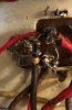
Thanks, Mark. I did that, clipping the multimeter lead to one side of the resistor and testing it with the other lead. As I increased voltage on the variac the voltage on the multimeter seemed to increase correspondingly, but after a few seconds--and before I could really tell what was going on--the resistor began to smoke . . . so I quickly turned everything off.
Not sure where to go from here. As I've said, the cap can seems pretty new and I doubt it would be the culprit.
Not sure where to go from here. As I've said, the cap can seems pretty new and I doubt it would be the culprit.
Moonwatcher
Active Member
Moonwatcher
Active Member
The only part of the amp that 10K resistor feeds is the driver circuit. So if you haven't tried powering up without the drivers in, try that to see if it will hold. If it still gets too hot then there is a short to find.
So I tried it without the driver tubes and the already fried resistor started to glow again. Do I need to try this again with a fresh 10K resistor soldered in? Thanks.
Moonwatcher
Active Member
Wow, thanks, but such resistance and voltage checks may be too advanced for me. This is the first time I've tried to work on this kind of thing and I can barely figure out the multimeter. I did hear that some new guy works on tube amps at a music store in town. Wish I'd studied this stuff in school.
Moonwatcher
Active Member
That's a good idea, although I'm not sure whether such groups exist in my area. Definitely worth investigating.
Moonwatcher
Active Member
Just an update, not to mention an EMPHATIC shoutout to Dave (dcgillespie), who suspected that the red wire connected to the can cap might be the culprit. It is one of the wires in the "umbilical" set of cords soldered into the 9303 preamp (original to the Maggie, but attached long after this amp was restored). When that was removed, a fresh resistor (R3 or R24, depending on the schematic) did not get fried and the amp has been working beautifully since. Since the preamp/tuner section must have a short, I'm just going to remove it and go with another preamp.
Meanwhile, the Maggie 9303 is back online and so much fun to listen to. Thanks again to everyone who helped me with this!
Meanwhile, the Maggie 9303 is back online and so much fun to listen to. Thanks again to everyone who helped me with this!
