

You are using an out of date browser. It may not display this or other websites correctly.
You should upgrade or use an alternative browser.
You should upgrade or use an alternative browser.
Maggie Console Rebuild: Chpt 4: 9304-20 Amp Refurb: Round One
- Thread starter Harlon
- Start date
-
- Tags
- 9304-20 amp refurb

In a pinch, you can actually make one. If its the typical #10-24 thread (confirm that, it might be 10-32 or 8-32), you can get a sufficiently long brass machine screw, lop the head off, and grind it to the right shape. Tin it, and you can get on with soldering for a while. You may also need a nut to serve to jam the tip in position. I don't remember if the ends of those Wellers are a blind hole or if its tapped all the way through. Its not ideal and probably won't work as good as the proper thing but any hardware store ought to have brass machine screws. For that matter, if its that 23 watt Weller pencil that they've been selling forever, the hardware store might actually have tips. Small local store is more likely to have it than a big box store.

Harlon
Active Member
gadget, I don't think I ever want to be that hardcore. Mine is actually one with smooth tips with a set screw. Either 35 or 40 watts.
I've got a couple tips on the way. Fun fact, paid the extra 33 cents for FedEx 2-3 day instead of USPS. Ordered on Wednesday. 3 days is Saturday so it gets bumped to Monday. USPS would have, maybe, gotten it here on Saturday. Maybe I'll get lucky. I paid for the FedEx cause last time I did USPS with this company it took a week.
I've got a couple tips on the way. Fun fact, paid the extra 33 cents for FedEx 2-3 day instead of USPS. Ordered on Wednesday. 3 days is Saturday so it gets bumped to Monday. USPS would have, maybe, gotten it here on Saturday. Maybe I'll get lucky. I paid for the FedEx cause last time I did USPS with this company it took a week.
Harlon
Active Member
Quick update on parts for the amp rebuild.
Had to order a few bits and pieces this week while ordering in some soldering tips.
I finally pulled the trigger on upgraded coupling caps.
I'm running .1 and .047uf.
For the .1uf I went with Auricap XOs, and for the .047uf I went with Vitamin Qs.
I'll let you know if they make a difference in anything but my budget.
Had to order a few bits and pieces this week while ordering in some soldering tips.
I finally pulled the trigger on upgraded coupling caps.
I'm running .1 and .047uf.
For the .1uf I went with Auricap XOs, and for the .047uf I went with Vitamin Qs.
I'll let you know if they make a difference in anything but my budget.
I like to buy things when practical, but once in a while you get into an emergency. The set screw ones are easy enough too, just need round brass rod of the right diameter. My Hakko tips I really couldn't even attempt to make without a lathe. Its got a hollow pocket in it where the heater element goes, and a shoulder where the retaining collar sits.
Harlon
Active Member
So, picked up my refurbed TT from the TV Repair guy today.
Had a happy accident when I got home. Moving things around on my bench I inadvertently disconnected a jumper clip from one of the speaker leads for the 6V6 I'm listening to right now. Couldn't figure out why one channel was dead,..., found the free clip. As I was trying to figure out which speaker wire from my Magnavox crossover and speakers I needed to connect it too, it's a bit of a nest, I realized that the speakers weren't hooked up properly. It seemed like the returns or negatives or whatever you call them with speakers were going to nowhere. I pulled the speaker diagram and low and behold two or three lines were in the wrong place or left out altogether.
The happy part is, I think I finally solved the mystery of the weak left channel. I may come back to this again later, but after wiring things up according to the diagram, it was like after cleaning the pots for the first time. It came to life all over again. Don't know if this is solved for good. I can only hope and relish in my happy accident.
BTW, TT looks great, can't wait to fire it up when I'm done with this chapter of the refurb. I went with farming out the TT refurb because I wanted it done right and didn't feel confident messing with all the little parts and springs and such. I barely have the fine motor skills and vision to pull off all the soldering. Looking at the service manual for the TT just made me want to cry a little bit.
If I'm lucky my soldering tips will show up tomorrow. Since I'm apparently not I'll be back sometime next week to continue this saga.
Had a happy accident when I got home. Moving things around on my bench I inadvertently disconnected a jumper clip from one of the speaker leads for the 6V6 I'm listening to right now. Couldn't figure out why one channel was dead,..., found the free clip. As I was trying to figure out which speaker wire from my Magnavox crossover and speakers I needed to connect it too, it's a bit of a nest, I realized that the speakers weren't hooked up properly. It seemed like the returns or negatives or whatever you call them with speakers were going to nowhere. I pulled the speaker diagram and low and behold two or three lines were in the wrong place or left out altogether.
The happy part is, I think I finally solved the mystery of the weak left channel. I may come back to this again later, but after wiring things up according to the diagram, it was like after cleaning the pots for the first time. It came to life all over again. Don't know if this is solved for good. I can only hope and relish in my happy accident.
BTW, TT looks great, can't wait to fire it up when I'm done with this chapter of the refurb. I went with farming out the TT refurb because I wanted it done right and didn't feel confident messing with all the little parts and springs and such. I barely have the fine motor skills and vision to pull off all the soldering. Looking at the service manual for the TT just made me want to cry a little bit.
If I'm lucky my soldering tips will show up tomorrow. Since I'm apparently not I'll be back sometime next week to continue this saga.

s-petersen
Scott
In a pinch, you can actually make one. If its the typical #10-24 thread (confirm that, it might be 10-32 or 8-32), you can get a sufficiently long brass machine screw, lop the head off, and grind it to the right shape. Tin it, and you can get on with soldering for a while. You may also need a nut to serve to jam the tip in position. I don't remember if the ends of those Wellers are a blind hole or if its tapped all the way through. Its not ideal and probably won't work as good as the proper thing but any hardware store ought to have brass machine screws. For that matter, if its that 23 watt Weller pencil that they've been selling forever, the hardware store might actually have tips. Small local store is more likely to have it than a big box store.
I've used 12ga copper wire in a pinch ground and flattened at the end(a long time ago)for the gun type Weller

crispycircuit
Super Member
My buddy uses brazing rod to make tips. Myself I just pay and wait. Never hurts to have spare.
Harlon
Active Member
Got my replacement soldering tips on Monday. Finally got a minute to continue work on the MPX.
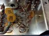
Here are a few extremely exciting pics of the replacement of the 4uf electrolytic C2 tying coil L1 with the L&R Gain Pot.
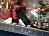
Above is the existing stock cap.
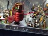
After removal. Extremely exciting.
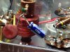
And here is the 4.7uf replacement cap,
I will note that when tested out of circuit the stock cap tested bad. Early on someone suggested that this cap was likely the culprit behind the MPX not working. Seems this may be correct.
Here are a few extremely exciting pics of the replacement of the 4uf electrolytic C2 tying coil L1 with the L&R Gain Pot.
Above is the existing stock cap.
After removal. Extremely exciting.
And here is the 4.7uf replacement cap,
I will note that when tested out of circuit the stock cap tested bad. Early on someone suggested that this cap was likely the culprit behind the MPX not working. Seems this may be correct.
Harlon
Active Member
Okay, so I've decided that my life is just not fit for projects of any sort. Jeez Louise if I could finish something it might be nice. I'm really not sure though because I never finish anything.
I could list all the paltry reasons for not completing this project by Thanksgiving as I'd planned, so I'm just going to blame Dave.
Dave had to go and start a work up on the 9300 series magnavox, so I'm stalling completion of my project until he's done so I can incorporate any upgrades or improvements he comes up with before I button things up.
I guess slow is actually working out, thanks Dave.
I could list all the paltry reasons for not completing this project by Thanksgiving as I'd planned, so I'm just going to blame Dave.
Dave had to go and start a work up on the 9300 series magnavox, so I'm stalling completion of my project until he's done so I can incorporate any upgrades or improvements he comes up with before I button things up.
I guess slow is actually working out, thanks Dave.
Harlon
Active Member
Finally got a little time to finish the MPX refurb.
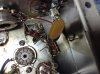
Ended up replacing the tube socket for the 6EU7 AF amp tube after all. While trying to clean-up the original, one of the eyelets let go of the base.
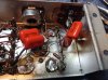
Wasn't too bad in the end. Only real trouble was putting the pair of 47k resistors linking the plates to the B+ line. They're the two resistors stacked to the right of the center prongs on the terminal strip on the right. First couple of attempts the wires kept shearing off when I tried to get a nice contact with the prong. Had to switch to a gentler set of pliers.
Hopefully this will have the MPX up and running. If you recall this was the only portion of the original console that didn't work when I got it.
Next will be tackling the Preamp and Smoothing Cap portions of the Tuner.
Ended up replacing the tube socket for the 6EU7 AF amp tube after all. While trying to clean-up the original, one of the eyelets let go of the base.
Wasn't too bad in the end. Only real trouble was putting the pair of 47k resistors linking the plates to the B+ line. They're the two resistors stacked to the right of the center prongs on the terminal strip on the right. First couple of attempts the wires kept shearing off when I tried to get a nice contact with the prong. Had to switch to a gentler set of pliers.
Hopefully this will have the MPX up and running. If you recall this was the only portion of the original console that didn't work when I got it.
Next will be tackling the Preamp and Smoothing Cap portions of the Tuner.
Harlon
Active Member
Okay, so Dave completed his intitial 9300 work up and mods. If I read it right I think he's going to do more with it later on. I hope he does a work up on an UL version.
Early on in my design process, in conversations with Dave about using EFB on a stock 9300, he wasn't totally sold on the benefits at least in regards to the limitations of the OPTs and overall design. I'm glad to see that his testing has yielded such good results. I originally just ordered the screen and grid resistors for my build. I was going to wait on the other parts in the event I upgraded to UL transformers.
For my build I'm going to fully incorporate the EFB upgrade as described in Dave's 9300 thread. On the phase splitter end, I'm going to use the scheme I developed prior to tear down. I really liked the quality of the sound I was getting from tweaking the NFB resistors and bypassing the Cathode Resistor. Not sure if these changes provide as much improvement as Dave's switch to floating paraphrase, but they definitely are audibly better than stock. My oscilloscope-ears like.
If for some reason, things don't sound as good after the refurb I'll likely switch to the floating paraphase. For now though I don't want to trash what I feel is a solid configuration. I was so hoping Dave would have explored this setup in his thread so I could see empirically if it is actually better.
Early on in my design process, in conversations with Dave about using EFB on a stock 9300, he wasn't totally sold on the benefits at least in regards to the limitations of the OPTs and overall design. I'm glad to see that his testing has yielded such good results. I originally just ordered the screen and grid resistors for my build. I was going to wait on the other parts in the event I upgraded to UL transformers.
For my build I'm going to fully incorporate the EFB upgrade as described in Dave's 9300 thread. On the phase splitter end, I'm going to use the scheme I developed prior to tear down. I really liked the quality of the sound I was getting from tweaking the NFB resistors and bypassing the Cathode Resistor. Not sure if these changes provide as much improvement as Dave's switch to floating paraphrase, but they definitely are audibly better than stock. My oscilloscope-ears like.
If for some reason, things don't sound as good after the refurb I'll likely switch to the floating paraphase. For now though I don't want to trash what I feel is a solid configuration. I was so hoping Dave would have explored this setup in his thread so I could see empirically if it is actually better.
Harlon
Active Member
Just read through this thread. Been 2 1/2 months since I picked up my soldering iron and worked on this project. Got through the holiday season at the wife's store and nearly finished with the master closet "refurb" we started last year. Looks like I'm going to get back to work on this in the next week or so. Printed Dave's 9300 schematic the other day. I need to go back through my build plans and make sure I have everything I need to complete the amp and preamp rebuilds. I know I used a couple of the EFB resistors somewhere else and I never picked up the trimmer for the EFB.
First things first. After completing the rebuild for the MPX I regretted tearing down the rest of the console because I couldn't do a live test to see if my work was successful. When I get back to it next week I'll start by wiring everything back up and seeing if the MPX is now functional. Fingers crossed.
Also, now that I'm down the road a bit, I'm torn about whether or not to go with Dave's floating paraphase mod. I think I'm going to go ahead and buy whatever parts I would need to make the change and run a comparison.
First things first. After completing the rebuild for the MPX I regretted tearing down the rest of the console because I couldn't do a live test to see if my work was successful. When I get back to it next week I'll start by wiring everything back up and seeing if the MPX is now functional. Fingers crossed.
Also, now that I'm down the road a bit, I'm torn about whether or not to go with Dave's floating paraphase mod. I think I'm going to go ahead and buy whatever parts I would need to make the change and run a comparison.
Personal opinion, but I find that mine sounds more accurate after changing the inverter. It was OK before, but just didn't quite bowl me over. Basically the amp sat on the shelf for about 2 years because it just didn't impress me enough to unhook anything else. Not that it was bad, but it wasn't displacing anything either. I've actually listened to it since revising the inverter stage.
Harlon
Active Member
Gadget, on the subject of your amp, I believe I read in Dave's thread that you made the EFB and inverter changes. Did you stick with the UL mode with your Edcors or converter back to a standard hookup?
Likewise, how would you describe the difference in your amp after installing EFB?
Thanks,
Harlon
I think I've settled on 1.) install EFB, 2.) make initial planned changes to inverter, 3.) change to floating, 4.) compare and complete installation of preferred setup.
Last fall Dave and a few others walked me through bypassing the cathodes on the AF half of the inverters and tweaking the nfb resistors which really brought my amp to life. I want to at least give it a chance before changing over.
Likewise, how would you describe the difference in your amp after installing EFB?
Thanks,
Harlon
I think I've settled on 1.) install EFB, 2.) make initial planned changes to inverter, 3.) change to floating, 4.) compare and complete installation of preferred setup.
Last fall Dave and a few others walked me through bypassing the cathodes on the AF half of the inverters and tweaking the nfb resistors which really brought my amp to life. I want to at least give it a chance before changing over.
Its running pentode mode currently. I was trying to hash out the lower than expected power output, and decided to duplicate the stock pentode setup to reduce variables. I think it got me about a watt. I don't know that it really sounds much different, but apparently my transformers don't have the optimal UL tap point anyway. Mine are 40%, and apparently what you want for a 6bq5 is 23%. Quite possibly about all it does is reduce power without giving much back.
Harlon
Active Member
Quite possibly about all it does is reduce power without giving much back.
 Nice, I thought you were running Pentode but wasn't sure. I'm still using the stock opts. I'm looking forward to see how it runs with the EFB hooked up.
Hopefully I'll get a chance to start digging into my notes tomorrow.