

You are using an out of date browser. It may not display this or other websites correctly.
You should upgrade or use an alternative browser.
You should upgrade or use an alternative browser.
Magnavox 169-BB mono block updates
- Thread starter TomD62
- Start date
I recently was given a pair of these monoblocks 169 BB. I intend to restore them as well. I'm looking to make them sound the best they can.
@TomD62 Did you change any of the values suggested or just replace with same values? I like what you did and am looking to do something similar.
@wparks You have given some insight on modding these. Can you take a look at this schematic I found in another thread? Does this information look correct? I'm seeing some values changed and some parts deleted. I'm looking at possibly purchasing both transformers listed as well.
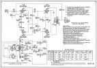
@TomD62 Did you change any of the values suggested or just replace with same values? I like what you did and am looking to do something similar.
@wparks You have given some insight on modding these. Can you take a look at this schematic I found in another thread? Does this information look correct? I'm seeing some values changed and some parts deleted. I'm looking at possibly purchasing both transformers listed as well.

It looks like many of the changes I had mention previously have been made- pulling the filters out of the feedback loop, primarily. This was to eliminate the funky tone tuning done to accommodate the ceramic phono cartridge. If it were mine, and considering installing expensive new output transformers, I'd probably change up the entire front end to use that second triode as a cathodyne phase inverter, rather than the somewhat pedestrian classical paraphase that it is now, but that's probably more of a radical redesign than you are looking for.@wparks You have given some insight on modding these. Can you take a look at this schematic I found in another thread? Does this information look correct? I'm seeing some values changed and some parts deleted. I'm looking at possibly purchasing both transformers listed as well.
I don't think the Hammond 1620 transformers specified here are a good fit at all- They have 6.6K plate to plate primary impedance, and the 6V6GT push pull with cathode biasing really shines at more like a 10K plate to plate impedance. This is also only a 10W maximum design, so an expensive 20W transformer is pretty overkill on the wallet for little upside. The Hammond 1609 would be better, and cheaper- has a 10K plate to plate primary impedance, and is rated for 10W which is fine here. (Runs about $30 each cheaper too.) The schematic you have listed is not using Ultra-Linear connections to the screens, so you don't need an Ultra-Linear transformer, so there are other good options, like from Musical Power Supplies, among others. Ask and there will be many suggestions here.
I would make a few tweaks to the shown schematic as well. C1, the 22uF shared 6V6 cathode capacitor needs to be larger- I like to use 100uF at least, rated at 100V or so, for better bass response. The R6 4.7Meg grid return for the first pentode is way too large (meant to accommodate the ceramic phono cartridge) and can be downsized to more like 470K so it's less noise prone. C3, the 22uF cathode bypass cap at the first pentode also needs to be significantly up-sized- more like 100uF or larger, at 25V is fine. I would not use 2W resistors everywhere, there is no benefit to that. On these old schematics if a resistor does not list a power rating consider it 1/2W (they usually used 1/4W). Most can be 1/2W and that is pretty bullet-proof, but if the resistor needs to be larger it will be called out in the schematic. Do yourself a favor and get a cheap, large 1% metal film resistor kit at Amazon rather than ordering each value.
A note about replacing the output transformers and the requisite need for feedback tuning- The schematic listed has R21 4700 feedback resistor with no frequency compensation capacitor parallel with it. This will likely result in some (or a lot) of ringing on the 10kHz square wave response depending upon what output transformer you finally settle on. Standard procedure would be to use a scope, signal generator, and dummy load to observe the 10kHz square wave transient response and experiment/iterate to find a good value for this compensation capacitor for the flattest high frequency response and best transient response. There may also be some concerns about the stability of the final amplifier without this equipment to test and verify it. This equipment and tuning is an inherent cost of modifying and customizing amplifier recipes away from tested and trusted recipes. If you don't have this equipment, this is just a one-off build, and don't want to go down that path, consider sticking with the stock transformers and tested recipes. Otherwise, there is lots of advice here on setting up and using your test rig to do this basic work, and lots of help if particular problems arise.
Last edited:
Thank you for taking the time to respond. A little background info. I do repairs on solid state receivers for the local shop. So I have a ton of parts already. Test equipment is not a problem either. I have a scope, 8ohm 200watt dumby load, freq counter, and signal gen.
I do think I want to get new output transformers and figure out the necessary changes. I'll test them tonight to ensure they do work. I am planning a total tear down with some painting required. From here Ill make my own thread to document the process and get any help required. Thanks again for taking the time to respond.
I do think I want to get new output transformers and figure out the necessary changes. I'll test them tonight to ensure they do work. I am planning a total tear down with some painting required. From here Ill make my own thread to document the process and get any help required. Thanks again for taking the time to respond.

split load inverter is one way to do it, if you're replacing the output transformers it will need re-tuning anyway. May as well make it a direct coupled split load to lose a phase shift point if you're going that route. direct coupled split load would look something like the front end of a Dynaco ST70 or Mark III.
Other option is floating paraphase. It would look something more like this, though I won't swear the resistor values are going to be correct. This is from Dave's re-work on the 8800. You're looking at the 430K, 50K pot, and 470K with the 3.3M across it. 50K is a balance pot, and could be eliminated.
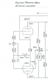
simplified arrangement without the pot
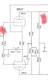
This provides a self-balancing action that the stock voltage divider setup does not.
Full 8800 schematic, obviously not a perfect match but it should serve as an example of what the whole thing looks like. You can do bias and balance if you feel the need, but I will suggest making sure the output idle current is reasonable. Possibly that cathode resistor will want tweaking to get the output tubes in a more optimal zone.

Other option is floating paraphase. It would look something more like this, though I won't swear the resistor values are going to be correct. This is from Dave's re-work on the 8800. You're looking at the 430K, 50K pot, and 470K with the 3.3M across it. 50K is a balance pot, and could be eliminated.
simplified arrangement without the pot
This provides a self-balancing action that the stock voltage divider setup does not.
Full 8800 schematic, obviously not a perfect match but it should serve as an example of what the whole thing looks like. You can do bias and balance if you feel the need, but I will suggest making sure the output idle current is reasonable. Possibly that cathode resistor will want tweaking to get the output tubes in a more optimal zone.

Before I tore into these I reviewed the schematic and checked to see if the installed component values matched the schematic, which they did. I ordered the resistors and capacitors and replaced / rewired just one so I always had the second stock one to fall back on for reference. These have been rewired to stock using the original transformers. I must say the bass response is much better than I was expecting, especially with the comments / recommendations that were provided by wparks and others.@TomD62 Did you change any of the values suggested or just replace with same values? I like what you did and am looking to do something similar.
Is there a way to find this out before I buy the Hammonds? Or will new ones be better regardless?I wonder if these may have better transformers than the stereo 6v6 amps
I attached the schematic I'm following to start. I tried a 470K in R6 it led to the music sounding veiled. Put the 4.7m back and it sounds clear. But it is out of spec showing 6m on my tester. I removed all extra stuff around C3 from the original schematic. I'm gonna listen to them this morning then figure out if I want to restuff the cap on top or just solder them in on the underside. Project is underway. Thanks for everyone's help so far.
Attachments
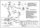
What is your music source? If you are using a modern source with low output impedance, R6 is invisible at even 470K. The only reason switching R6 to 470K affects the sound is if the source impedance is much greater than 470K. The reason I suggested that change is that 4.7Meg leaves the input so lightly held when source is disconnected and left open that it becomes very noise prone.