• The move to the new server is done. There are some software and database maintenance updates in process. This has us passing the hat around to help out. We appreciate any donations. Seriously, even a dollar helps. The payment page may be found here - https://www.audiokarma.org/support.html

Magnavox 2st660s Console Restoration with David Gillespie's 9300 Modification (Project Thread)

blknd_vggs

New Member
Welcome to my project thread! Sorry in advance for the long intro, but I feel like some context helps. I've organized the post into sections for easier reading.

- Prologue -

Newbie here with my first major hi-fi stereo project! As such, I want to document my project as I go. As someone who is a long-time tinkerer and diyer, but who's far from an electronics expert, I hope this thread can be a resource for anyone else considering a similar project! My goal, outside of having a working restoration and upgrade of this Maggie, is to get more confident in this hobby, understand things conceptually, and have some good nerdy fun.

- Backstory -

I've been slowly restoring a lovely Magnavox 2st660s console that's in the possession of my partner as a family heirloom. The console has a 57-12-00 tuner, 93-02-00 amp, micromatic turntable, and utilizes a pair of horn tweeters with 15" woofers. For some time, the console played alright, and per my partner's father, it had been serviced "recently" but certainly showed signs of age when listening to it (using FM radio and tape/aux input from 1/8" to RCA, but the turntable does not function...for now).

After my partner and I began using the console more, I noticed the audio levels in each channel were not balanced. Also, the pots on the preamp/tuner we crackly... to be expected for a unit that was seldom used. I gave the pots a light cleaning, which seemed to help. Then, after some more use, the audio output started to crackle, scratch, and pop at random times until it became far more frequent... Most recently, after the system warms up a little (less than a minute or two), the crackles occur and remain until I power off the unit. These crackles are loud, persistent, and independent of the volume level. The sound is hard to describe, but it seems like the distortion "surges" or "rolls" through the circuit. I began to suspect that the "recent" servicing her father had mentioned was either not so recent or not so thorough.

I opened the console up to see what I could find. The 9302 had not been touched since it was made in the 60s. The tuner does appear to have some newer components (to my relief!). So I scoured the many threads about the 9302 and while I'd love to tweak, tinker, and improve upon the original design, I figured I'd start with simply restoring the amp to near original spec... Well, that plan has now changed a bit...

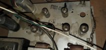
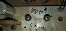
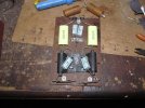
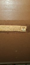
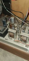
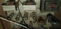
Some pics of the amp before I removed it. NOTE: A lingering concern I have is what appears to be staining from melted transformer potting compound?? I would assume it must have been running rather hot for this to happen... I'd love an explanation if anyone has any clues.
20250606_122251.jpg20250606_122001.jpg20250624_185606.jpg20250624_190430.jpg20250624_190437.jpg20250624_190442.jpg

- Restoration Begins -

For the 57-12-00, I've not touched the tuner aside from dusting and thoroughly cleaning all of the pots, power switch, and selectors since those were all scratchy and sticky. No more issues there after cleaning.

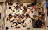
For the 93-02-00, I first cleaned the balance and hum pots thoroughly and then replaced all electrolytic capacitors with modern equivalents. Then I went through and cleaned the tube pins and sockets. For all pots and tubes I've stuck with Deoxit D5. After hooking up the amp to test my work, the crackles persist. I confirmed all solder connections... no issues there.

9302 with replaced electrolytics:
20260127_124515.jpg


- Narrowing Down the Problem -


Without any testing equipment, aside from a decent DMM, I think I've narrowed down the issue to it being related to something along the Channel 1 circuit:

1. I flipped the left-right speaker connections to see if the crackles would follow and they do.

2. I've swapped the 6eu7's around (V4 to V1) - no changes

3. Flipped the 6bq5 pairs (V2 and V3 swapped with V4 and V5) - no changes

4. Amp voltage testing with the tuner and amp removed from the console but hooked up to a 4 ohm dummy load - I confirmed weird voltages along the channel 1 circuit

5. I do not have a way to test the tubes, but no red-plating has been observed. A gentle tap of the tubes during operation reveals no harmonics as far as I can tell

6. Wiggling one of the 6bq5s in the channel 1 circuit did produce a similar and exaggerrated harsh crackle - hmm

7. Tightened all contact pins in the 9 pin tube sockets and even the octal (just for the hell of it) - no changes

- Current Project Status -

After realizing I may need to replace tube sockets and everything soldered to them, I figured it may be easier to just gut the chassis and start the build from nearly-scratch. Admittedly, I also couldn't stop myself from wanting to give Dave Gillespie's 9300 mod a try. Still, I wanted to keep this console as stock as possible. In another thread, I posted inquiring about whether this is even possible? Would the upgrades play well with the stock tuner and horn/woofer setup? Consensus from some AKer's who have experience with the Dave's 9300 mod believe it will, but the stock speakers and their current crossover setup may leave me with more to be desired. New crossover coming down the line?

For now... we move forward with the Dave's latest mod update from 12/2025! Since I'm going to be starting pretty much from scratch on this build, I'll be replacing all resistors, capacitors, and tube sockets. The hum and balance pots will be switched out for the EFB pot or resistors, respectively. Transformers will remain stock and I will not be doing any of the bucking mods since I will need to use the wiring harness.

To help me better grasp how the mod schematic maps with the actual wiring of the amplifier, I took some time to "port" over the modded schematic to a SAMS schematic for the 9300 series amps. I'm pretty proud of this haha, but I would greatly appreciate it if someone can check my work! I'm having a hard time figuring out how the second channel output tubes are connected so that I have two bias test points (one for each output channel). I know I need another 10 ohm resistor to the cathodes of these tubes... Please advise!

Dave's 9300 mod on a SAMS schematic:
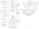

9302 schematic Mod edit.jpg
Link to Hi-Res PDF here!

Any and all suggestions or advice are welcomed and appreciated! More to come...
 
Register to hide this ad
Howdy @blknd_vggs -

Thank you for the build thread, the detailed writeup, and for the pictures- they really make the thread interesting and are helpful!

The big clue you have on the crackling is wiggling the 6BQ5 tube. The stock sockets for the 6BQ5's are actually really good. Unless you are replacing them with similar Belton sockets, the replacement is likely a step down in quality. Most new Chinese sockets use inferior metal connections, so tend to loosen and hog out over time. If you want to replace them with Belton, you can get them here at Amplified Parts. The sockets you really want to replace are those phenolic wafer sockets under the 6EU7 tubes- those were very cheap to begin with, get brittle and break really easily.

Since you have cleaned the tube pins, and socket connections, and checked all of the solder connections, and swapped the tubes, but wiggling the 6BQ5 continues to make the sound, I suspect a flaky carbon composition resistor. Not much else unless you missed it. You have tried all of the things I would suggest.

On the 9300 mods. I would suggest finding the crackling problem and resolving that, and getting the stock amp working correctly before you consider a rip-up and rebuild. Maybe the rebuild fixes it, maybe not, and you have the same frustration after a LOT more work. Since you are not modifying the power transformer connections for the bucking winding, there is no reason these Gillespie mods would interfere with the amp's operation inside the console- But keep in mind, these mods were necessary to bring the amplifier up to snuff for operation as a high-fidelity stand-alone amplifier- To be stable using a wide variety of possible speaker loads, have reduced hum, and much higher bandwidth and lower distortion to be able to reproduce adequately very high quality sources, with better power and lower distortion into better modern speakers.

Within the console, it has a safer, fixed environment with more limited requirements- amplify the noisy low quality radio and crystal phono (or 8-track) sources just well enough to reproduce them into the stock cabinet/speaker solution, which greatly lacked the fidelity and bandwidth of modern speakers (even if you put in better crossovers- the problem is the bandwidth and quality of the speakers/horns themselves). I say this, because doing all of this work will be somewhat lost behind the limitations of the existing sources and speakers. I recommend if you are going to do all of this work, that you take advantage of (or add) the ability to connect better external speakers- that way you can still enjoy the operation of the original console, then flip the switch and enjoy the full hi-fi benefit of these mods. Hopefully you can pipe your better sources right into the power amplifier- using the better speakers I think you will find piping your modern source through the rather pedestrian tone controls in the tuner chassis may be a disappointment.

Cathode connection- The two tied together cathodes for one channel connect to the output of the LM337 regulator through a 10 ohm resistor. The other channel does the same- cathodes tied together, connecting through a second 10 ohm resistor to the regulator output. Generally you will want three test points- one will be the output of the LM337, and the other two will be the tied cathodes of each channel. The measurement is taken from the output of the LM337 to each cathode pair, and you will adjust the regulator until you get 0.44V average across each 10 ohm resistor (indicating that 44mA is flowing from each channel into the regulator, or 22mA per tube.) In reality the tubes will never be perfectly matched, so the two channels will measure differently, so try to split the difference, centered on the 0.44V.

A very simple modification of this would be to put a 10 ohm resistor between each 6BQ5 cathode and the output of the LM337, so you could monitor the cathode current from each tube individually. Given that you only have one voltage adjustment for the bias voltage that is given to all four cathodes, (and cannot adjust individual tubes or channels), the extra monitoring would just be academic, but it is more informative as to how well each tube is matched with the others.

The transformer staining- This is very common on these console amps. Almost all have that to one extent or another. It's not so much about the wax melting due to overheating- In prolonged operation, particularly when jammed up against a wall, with years of dust accumulation blocking air low, temperatures do get high, the wax softens, and the oils migrate out of the wax and spread out over the chassis. Unless you see damage to the transformers themselves, usually significant darkening and burnt smell, they are probably fine. The oils will clean up easily with some lighter fluid, WD-40, or paint thinner, etc. If you are concerned about overheating- The transformers over time will get pretty warm to the touch, but you should be able to touch them. Too hot to touch would be a concern. Also, you can measure the voltage across the ceramic 100 ohm shared cathode resistor and we can see what bias current your four 6BQ5 tubes are pulling- that will help a lot to indicate if there is an overheating problem.

Many of us here have enjoyed building this amp, and will be able to answer any questions you might have. Thank you for starting a build thread!
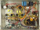
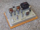
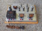
My 9300 build is shown below. I mounted a recessed pot on the side for the bias adjustment, and tip jacks hidden behind the power transformer for monitoring.
 

Attachments

  • DSCN4085.JPG
    DSCN4085.JPG
    181.9 KB · Views: 37
  • DG_Maggie_9300.JPG
    DG_Maggie_9300.JPG
    189 KB · Views: 34
  • DSCN2867.JPG
    DSCN2867.JPG
    189.6 KB · Views: 34
A two-way crossover that doesn't run the woofer full range will help a lot here. Stock there is a lot of overlap in the middle f the band. May also benefit from adding a tweeter to carry the highest bits. The horn is a pretty good midrange but doesn't go way up.
 
Hey @wparks !

I appreciate your thorough reply! I did already commit to getting new compenents for the mod and this included new Belton sockets to replace all of these old 9 pins. I even got a Belton octal socket to be thorough and get it all to a fresh starting point. However, just for my own piece of mind and in an effort to learn, going through the amp more thoroughly to identify the problematic component does seem worthwhile. I'll give checking the resistors a more earnest go and report my findings!

I figured that even if I end up with a few extra or unused new or old (good) compenents from the teardown and rebuild, then no biggie. I intend to have other projects in the future because this stuff is a lot of fun. If I have some extra parts on hand that I can utilize in the future, that's fine by me!

I love the idea of being able to use the console in its stock-modified form, but with an external speaker option for listening to other sources. Conceptually my goal is blending a capable vintage console with a hi-fi option. This feels like a better use of this modded amp. My partner wants to use the console to output audio from their TV when watching shows/movies or streaming music along with the ability to use the console radio and turntable. I know there are limitiations with the stock speaker setup, especially with the use of these more modern source uses, but I wanna have my cake and eat it too and it seems like not the worst idea! Perhaps im having delusions of granduer? I dunno, but it sounds fun to me. Feel free to talk me down to reality though!

Thank you for clarifying the LM337 and 10 ohm resistor question and I will take your advice on the test points and recessed balance pot. I have a 5k pot already, but having a recessed knob woud be preferable.

The transformer explaination is very helpful. I hadn't seen any indication of serious issues there when the amp is powered on, but I wanted to double check!
 
Last edited:
A two-way crossover that doesn't run the woofer full range will help a lot here. Stock there is a lot of overlap in the middle f the band. May also benefit from adding a tweeter to carry the highest bits. The horn is a pretty good midrange but doesn't go way up.
I am also in the middle of a similar maggie console overhaul. Record changer and everything. I like your suggestion about swapping out the crossover. Makes perfect sense to me. I will be following along on this.
 
I saw posts on another site years ago where someone cut out the front speaker baffles leaving just a few inches around the baffle intact.
Then made new grills attached to what was left of the old speakers baffles.
He slid some nice bookshelf sleakers into the console from the back.
I still have the 15" woofers and horns from a beat up console I stripped the 9303 amp out of. Those horns rolling off at 12K was noticeable. The console was working when I got it, so I gave it listen before stripping it.
 
A two-way crossover that doesn't run the woofer full range will help a lot here. Stock there is a lot of overlap in the middle f the band. May also benefit from adding a tweeter to carry the highest bits. The horn is a pretty good midrange but doesn't go way up.
Adding a tweeter to the console is another interesting idea to consider... I have some time before I get to that stage of the project, but I wonder if you have any recs for possible tweeter options?
 
Nothing in particular, on the rare occasion I've meddled with speakers its been a case of seeing what I had, or what was available for reasonable money. My own console (not a Magnavox) has a set of Vifa dome tweeters in it. The originals were just really crappy paper ones. A lot of it will depend on the space and how you have to mount them.

From doing a google search I found this. Magnavox Horn Specs... Not sure I can hear much over 12k at my age anyway. Another set of tweeters could be added but I am fresh out of 3 way x overs at the moment.

A simple cap in series with it to roll off below maybe 12k and wire it in parallel with the stock horn may be all it needs. Or if it doesn't sound overly dull on top, let it be. Can always start with a simple 2 way and add/modify from there if needed.

He slid some nice bookshelf speakers into the console from the back.
also a good option if its one of the consoles that lends itself to this. Some of them aim the woofer out the side and have the horn in front without a wide enough grille to really allow for front-firing speakers. Not sure what it would sound like having them just aimed out the sides.
 
Hey all,

- Channel 1 Distortion Problem -

The other night I went through all resistors to check their impedance and confirmed that the resistors on my problem channel side have drifted up. Nothing too significant, but there were a few that had drifted far beyond where the resistors along the Channel 2 circuit had drifted. Glad I checked!

Still, with the new parts on hand, I'm going to stick with my mostly-from-scratch rebuild. Rather than waiting on another order of stock-value resistors to fix this problem, I want to get moving on this build.

- Schematic Update -

I corrected the schematic per @wparks suggestion, it now includes a 10 ohm resistor between both sets of output tube cathodes. I have the LM337 output connecting to each of those same 10 ohm resistors.

Question: Is it correct that the LM337 output also connects to the two 220k resistors off of the power transformer? In my mind that all makes sense, but if someone can check my work... please do!
 
Last edited:
Question: Is it correct that the LM337 output also connects to the two 220k resistors off of the power transformer? In my mind that all makes sense, but if someone can check my work... please do!
Yes- That is the replacement for the hum balance pot. Those resistors go across the 6.3V filament to a virtual center point that is elevated to 6BQ5 cathode voltage by connecting to the regulator output.
 
Nothing in particular, on the rare occasion I've meddled with speakers its been a case of seeing what I had, or what was available for reasonable money. My own console (not a Magnavox) has a set of Vifa dome tweeters in it. The originals were just really crappy paper ones. A lot of it will depend on the space and how you have to mount them.


A simple cap in series with it to roll off below maybe 12k and wire it in parallel with the stock horn may be all it needs. Or if it doesn't sound overly dull on top, let it be. Can always start with a simple 2 way and add/modify from there if needed.


also a good option if its one of the consoles that lends itself to this. Some of them aim the woofer out the side and have the horn in front without a wide enough grille to really allow for front-firing speakers. Not sure what it would sound like having them just aimed out the sides.
I ended up recapping the stock xo and am happy with the sound for what it is with the stock drivers. The lows and highs are more defined and separated with not so much of the midrange harshness that was there before. The original caps read ~13uf, btw
 

Attachments

  • IMG_2466.JPG
    IMG_2466.JPG
    147.5 KB · Views: 21
Looks like a proper crossover with chokes, mine have mostly been a single cap to keep lows out of the tweeters and the woofer just runs full range with lots of overlap. Lots of room for improvement when the start point is basically nothing
 
Hey all!

- Build Update -

Good news! I've been chipping away at this 9302 refurb/mod whenever I've had little bits of free time and I've gotten it mostly complete! However... Not so great news! I'm having some (high voltage?) issues around the EFB circuit, but more on that later.

***See "Testing, Issues..." and "Current Satus" sections in my next post to tldr for more troubleshooting***

Since this thread somewhat of a project journal, I'm documenting the steps, including the mundane or obvious ones, and some narrative about the process. Hope it's somewhat entertaining at the least.

- Chassis Mods -

In my earlier post, I decided that I wanted to go ahead and start this build mostly from scratch. While this would require more work, I wanted the opportunity to practice different skills and to use new components that will, hopefully, last for years to come.

Specifically, I wanted to at least remove the cheap 9-pin phenolic tube sockets for the phase inverter section. The other 9-pin sockets for the output tubes and 8-pin for the rectifier were in decent shape, but some the pin contacts were pretty loose, worn, and showed some corrosion. So I decided to replace those with new Belton components.

20260310_211542.jpg

Consequently, this meant stripping out almost all components which allowed me to more easily clean up the chassis, drill new holes (fuse holder and tip jacks), use sturdier fasteners in place of the original rivets, and put in place new loop ring terminal strips for easier lead dressing. All new fasteners are #4-40 zinc plated screws with kep nuts. New chassis ground points are thread-tapped holes for #4-40 screws and soldered for optimal continuity. I used a 300w soldering gun for all of those new chassis grounds. Additionally, I had to drill out the chassis a bit more for the replacement octal tube socket since the new one was slighty larger than the original.

I took a good amount of inspiration from wparks when it came to terminal strip placement You can also see that I replaced the RCA input jacks. To mount those jacks I used the original piece of phenolic board. I relocated it from under the chassis to the top and drilled out the old RCA holes in order to gain a little more spacing in between each jack. Putting the phenolic piece on the top side gave me better spacing for mounting everything. The RCA common/ground tabs were simply soldered where the original jacks were soldered to the chassis.

For the bias test points I'm using 3 tip jacks. One tied to the output of the lm337 regulator and the other two are tied to each 10k bias resistor. The holes for mounting the tip jacks were drilled and panel mounted behind the stock output transformer. I still have two more jacks I'd like to add, enabling easier measurement all 4 output tubes to see how each individual tube is behaving.

For the bias pot, I have removed the hum pot and replaced it with a 10k linear bias pot. The original balance pot was removed since it's no longer needed.

I also added a hole to mount a fuse holder for the recommended 2A slow-blow fuse.

For all of the chassis drilling I used a hand drill with a decent step bit. A drill press would have made my life a lot easier, but I'm working with limited space here in my apartment.

- Power Section -

The only somewhat tricky bit here is retrofitting the original molex plug wiring to the Dave's circuit design. This was done so that I can still send power to the original preamp and tuner by utilizing the "umbilical" harness.

Everything else was pretty straightforward. With the power section in place and continuity confirmed, I briefly powered up the amp on a 40 watt dim bulb tester to make sure nothing was obviously done wrong. I did this both with the rectifier tube installed and with it removed. No clear voltage outliers or catastrophic failures! I have since replaced that massive orange drop poly cap with a XY safety cap... I dunno why I wanted to use that poly cap other than it was around from a salvage piece and it has the correct capacitance.

20260310_211527.jpg20260310_211532.jpg20260313_001828.jpg

- Output Tube Power and EFB Section -

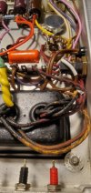
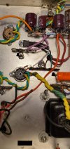
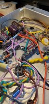
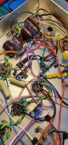
This is where things get a bit more complicated for me. I was, and to be honest, still am having a hard time understanding how the bias regulator and bias pot should be wired up. You can see how I wired it all up below.

20260310_211535.jpg20260313_001828.jpg20260313_001833.jpg20260313_001908.jpg

Some resistor leads were insulated with shrink tubing In locations where exposed leads may contact other leads to avoid accidental shorts.

I did my best to use some color continuity with my lead dressing. I found doing so really helpful when checking my work against the schematic.

Once everything was soldered in and continuity was checked around my solder connections, I moved on to powering up the amp on my dim bulb. Again starting on 40 watts, I powered up with the rectifier installed. Voltages looked safe so I pressed on. Another 40 watt dim bulb power up with the output tubes in place. Everything was still looking pretty good. I'm keeping in mind that I'm not running full power so I cannot say for sure that voltages are 100% correct. Just looking for catastrophic or obvious issues.

20260310_211444.jpg20260313_001502.jpg20260313_001525.jpg

Continued on the next post...
 
... March 31st, 2026 update continued

- Input and Phase Inverter Section -

Again, pretty straight foreword. Having taken the time to make my own version of the modfied schematic, it really made things so much easier when I went hands-on with the build.

Once I was satisfied with my lead dressing and solder connections, I moved on to the testing phase.

20260325_185724.jpg

- Testing, Issues, and a Burnt Pot -

** As a newbie, I have only my little DMM to measure anything on this project. For protection equipment, I have a homebrew dim bulb tester (limiter) that I made as well as a two-channel 4 ohm dummy load rated for 150w. My DBT design allows me to use 40 watt incandescent bulbs in series to, in theory, check for shorts and bring the DUT up to full mains power in steps. I have a digital ammeter on this DBT to give me somewhat of a better sense of the power my DUT is pulling from my mains source. **

With all tubes installed, amp connected to the tuner/preamp, and dummy load hooked up I was anxiously ready to see what I had done or didn't do right. I plugged in the power cable of my 9302 to my DBT and prayed to the amplifier gods before switching it all on.

40w DBT switched on, bulb lit, and I saw a slight dim of the bulb. Nothing catastrophic! Good start! Probing around with my DMM and again I'm not seeing anything extraordinary.

Feeling bold, I decided to switch on my second 40w bulb in the series. My bulbs dim further and I watch DC voltages on my filter caps rise a bit more. Looking good! I'm cautiously excited at this point!? I let the DUT settle there for a bit. After a few minutes, I begin to hear a sizzle... Odd. I see whisps of smoke exiting my bias pot... ****. I flip the main power switch of my DBT off and pull the plug to my DUT.

- Current Status -

So here I am presently with this project. I've gone through the schematic and re-read forum posts about the EFB. Tried to figure out what I've got wrong. I've looked at the voltages around the EFB circuit, but without running full mains power, I cannot determine for sure what my voltages are measuring compared to the expected outcome. I'm hesitant to run the DUT under full mains at risk of damaging other components.

In my search for ideas or others with similar issues, I found a correspondence about a failed LM337 and followed Gadget's suggestion there on how to test the regulator. My measurements do not seem to indicate a regulator failure.

All that I can tell is that it seems like too much voltage is going to the bias pot, but I've hit a bit of a wall and would greatly appreciate guidance from here!

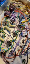
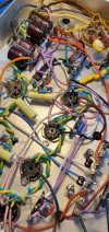
Pictures below from slightly different angles to check my work:
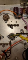
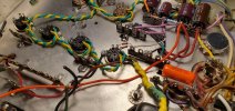
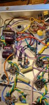
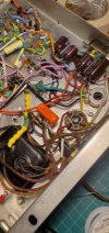
20260331_121417.jpg20260325_195155.jpg20260331_121446.jpg20260331_121500.jpg20260331_121505.jpg20260331_121515.jpg

I'll be happy to take closer shots of any sections that may be hard to see. Thank you to anyone remotely interested in this and thanks again to everyone who has offered advice thus far!
 
Last edited:
There are basically two octal socket sizes, the common one that wants a 1 1/8 hole, and the less-common 1" one. I don' know of a source for new, small diameter octal sockets but you can find them NOS sometimes. I bought a bag of mixed NOS octals and 2 happened to be the oddballs. I squirreled them away as spares for an amp that I own that uses them.

anyway, it looks like the purple wire is your screen supply? if so it looks like its wired sanely and I can trace the circuit through the pot to the EFB reg and that looks right. Can you confirm the values of the two resistors I have circled, and the value of the pot itself? About the only reason the pot should emit magic smoke is if its got too much current, and that should only happen if those resistors are much smaller value than they ought to be.

also not sure if you saw it but there is a reliability update for the EFB reg in these,


1774989257487.png
 
Hey @gadget73 thanks for the quick reply! I did base my EFB off of the latest update. However, I made a rookie mistake... go figure! I apparently ordered a 330 ohm 2w resistor instead of a 330k 2w. So at the moment I have a 330 ohm 2w resistor trying to tame the screen supply. I imagine a 330k should help not fry my pot. I'll replace that and report the results!
 
Back
Top Bottom