• The move to the new server is done. There are some software and database maintenance updates in process. This has us passing the hat around to help out. We appreciate any donations. Seriously, even a dollar helps. The payment page may be found here - https://www.audiokarma.org/support.html

More Fun With Magnavox: The 9300 Series

The stock Magnavox bias point isn't particularly abusive so they may be OK. The tubes I was initially testing with were old RCA that i had pulled out of a trashed organ I found on the side of the road a long time ago. No clue how many hours or what sort of abuse they suffered. At the time it was the only matched set I had which weren't misbehaving in some fashion.

The set in it now are also used pulls from a Metz console amp. It might squeak a wee bit more from brand new tubes but I seriously doubt it would make enough more to care about.
 
I have been really surprised that the tubes I have pulled out of several 1960's consoles and the like have tested almost new in terms of emission strength. I don't think these consoles got nearly as many hours as say the family TV, and as records and 8 tracks faded away (as did radio listening) these tubes sat unused in storage most of their lives. I would test them, you might just be surprised.
 
Wow, great thread! Finally made it through, tho I admit to just skimming some of it.

Been out of the game for a while; are the Z-565 clones unavailable? I picked up a really nice console with a 9302 amp; I’ll rebuild with the Z-565 if I can, if not I’ll use the Edcors with gadget’s circuit. But I would really prefer the Z-565.

edit - corrected typo, amp is 9302, not 9202
The original Magnavox output transformers are not terrible.
I like them, and I'm not even sure I don't prefer them to the Z-565 in my Dynaco ST-35.

They do roll off at bit at the ends, but I don't care about the high frequencies as I can't hear them any more.
The low end, I have multiple subwoofers.
 
The original Magnavox output transformers are not terrible.
I like them, and I'm not even sure I don't prefer them to the Z-565 in my Dynaco ST-35.

They do roll off at bit at the ends, but I don't care about the high frequencies as I can't hear them any more.
The low end, I have multiple subwoofers.
Changing the value of the coupling caps does help with the bottom end.
My hearing only goes to 14Khz now, so I don't notice anything missing in response at the lower high end with the original OPT's,. I wound up leaving the original OPTs in mine as well. They do sound sound good.
 
I got around to testing the 6BQ5s on my Hickok; two tested strong, one good, and one limped in at less than 50%. That one looked bad with dark glass, so I wasn’t surprised.

The 6EU7 from the tuner/pre tested well, I’ll likely add the buffer and a volume control to the amp, to make it a stand alone unit that can be run off of a CD player or DAC without a pre.

Going to try the 15” woofer on an open baffle, with the RP109 horn and an added supertweeter. Not great sound, but should be good sound for really cheap. I’ll give it to some young guys I know to get them hooked.
 
Based upon my experience with the 9300, you really don't need to add a tube buffer to have a volume control and make it stand-alone. I love running it direct from a high quality source.

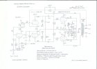
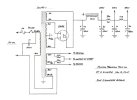
On the first attempt I replaced the 470K with a 500K pot, and Dave G. indicated that when the volume was turned to a low level, that would put a large series resistance between the source and the grid of the input tube, causing high frequency attenuation due to the miller capacitance. He suggested if I did not want to add a buffer I could use a lower value for the pot. I have found that 10K audio taper (great one here at AES) is perfect- it's very easy to drive from any likely source, yet presents little series resistance to the grid. When I use the amp with a pre-amp I just put the volume all the way up. The 470K grid return resistor as shown is a great insurance policy in case the pot ever gets dirty/flakey. I have found that there is no perceptible high frequency loss, and it works great.


1752879229330.png DSCN2862.JPG
 

Attachments

  • DCG_9300_Channel_Schematic.jpg
    DCG_9300_Channel_Schematic.jpg
    92.3 KB · Views: 57
  • DCG_9300_PowerSupply_Schematic.jpg
    DCG_9300_PowerSupply_Schematic.jpg
    58.4 KB · Views: 55
The buffer helps when using a high value pot to eliminate the Miller problem. 10k won't have any Miller effect problems, but not all sources can drive that. All depends what you need.
 
I probably should test my 9300 and make sure the pot doesn't affect bandwidth at very low settings- but then again I bet the stock transformers probably roll off before I would see it. Would be interesting to do for the 100K as well.

Most modern sources have an output impedance well below 1K, many much lower than that, so no problem either way. Some vintage tube pre-amps have really sucky high output impedances of 10K or above, like the original Magnavox radio/phono tuners that drove these amps originally (that did not have a follower output). That's why you so often see 100K to 1M potentiometers, which I tend to always avoid due to possible noise sensitivity.
 
NOVEMBER 2025 EFB™ SCHEMATIC UPDATE

Other threads with discussions regarding this amplifier have wondered about applying the latest EFB updates to it, when I noticed that neither of the schematics for either version (using original Magnavox OPTs or using Z-565 OPTs) had been updated for even the original (but now outdated) EFB update. My apologizes for not doing so before now! So here are the updated 2025 schematics for both versions for those who wish to make them, which is highly recommended. The December 2025 date on the schematics simply represents the amount of time it took since November 2025 to get the schematics redrawn and posted. For both schematics, the updates are identical, and include the following changes:

1. The 330K 1W resistor is upgraded to a 2W metal film device of the same value. This change was made only in the interest achieving maximum stability of the circuit in a widely varying temperature environment. The original 1W part was well rated for the dependability of the resistor, since it only dissipates 0.37 watts, but a 2W rating acts to enhance the stability of the resistor's value as its temp and the ambient temp it operates in moves from ambient conditions to operating temperatures.

2. A 430Ω 2W resistor is added between the Output terminal of the regulator, and ground. As a side benefit, this resistor acts to reduce the operating temp of the regulator -- which never has been a problem -- but also primarily acts to help protect the regulator in the event of a catastrophic tube failure (screen arc) event. If the previous EFB update was installed using a 200Ω resistor at this location, it should be removed and replaced with the new 430Ω value recommended.

3. A 3.0 volt 0.5 watt Zener diode is now added between the ADJ and OUT terminals of the regulator, with the banded end connected to the regulator's ADJ terminal. If the previous EFB update was installed using an arrangement of four small signal diodes, they should all be removed and replaced with the single new recommended diode. An appropriate Zener is manufacturer's part number BZX79-B3V0,113 which widely available at numerous parts houses.

These changes provide the same protections for the regulator as the earlier update did, but do so without the unintended influence with regards to ambient temperature changes that the earlier signal diodes potentially caused. For those who have made compilation threads highlighting the most important parts of this thread, please add this post to those threads. Thank-you!

Happy Listening!

Dave

Updated schematics:

Below: Using the original 9300 OPTs:
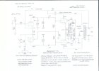
2025 Magnavox 9300 Update Stock Xformers.jpg

Below: Using Z-565 OPTs:
2025 Magnavox 9300 Update with Z-565 1.jpg
 
Thanks for this update Dave.

I had been wondering if something was wrong with my build when I noticed that the bias current would climb as the amplifier heated up. The bias current is very stable now.
 
.. It still has the original Magnavox stencil ‘West Germany’ EL84s; I haven’t tested them, but I imagine they’re pretty tired.

I have been really surprised that the tubes I have pulled out of several 1960's consoles and the like have tested almost new in terms of emission strength. I don't think these consoles got nearly as many hours as say the family TV, and as records and 8 tracks faded away (as did radio listening) these tubes sat unused in storage most of their lives. I would test them, you might just be surprised.

This is my theory as well, just got my 9304 back from the shop and it's good to go not to mention all the tubes tested strong.
 
This is a very timely update as I am about 90% done with the modification to a 9302 with original output transformers. Glad I saw this. :cool:
 
I just got the amp several weeks ago and it's stock, all my tech did at this point was assess and test so yes the OPT's are original
The originals sound pretty good. Although 4 ohm speakers probably would be best since the secondaries are 3.7 ohm I believe. But mine sounds fine with 6 and 8 ohm speakers.
 
Last edited:
The originals sohnd pretty good. Although 4 ohm speakers probably would be best since the secondaries are 3.7 ohm I believe. But mine sounds fine with 6 and 8 ohm speakers.
Correct. Pretty good stock iron. A ~4 ohm speaker load is what was used in the original consoles. An ~8 ohm load will work but will likely have less volume output. I am in the middle of another Maggie rebuild right now.
 
Last edited:
Had a 9300 on the bench today testing it. Have probably seen this thread before, but of course forgot about it. Very happy to find it again. Thanks much @dcgillespie!!

 
Hi all, I'm a little late to this thread (just a bit!) but am building my own 9300 now and have some questions.

First off, I went ahead and built Dave's buffer stage but I would like to add a volume control. I am unsure whether I should add it before the circuit or after the buffer. Also, which value should I use for the dual gang pot? I currently have 10k and 100k audio taper pots I can use, though I've seen on this thread someone using a 500k pot that leads the buffer stage and replaces the 470k ohm resistors that come off the source input jacks.

Any suggestions, or better yet a schematic, would be appreciated!

Second, I know the solution to the hum pot delete is to ground the signal wires going to the grids of unit 1 the 6EU7s with 390 ohm resistors, but looking at Dave's schematic for the buffer stage it appears those have been replaced with 470k ohm resistors to ground. Is this true, or should I still add 390 ohm resistors IN ADDITION to those? I also notice that some earlier versions of the buffer stage use a 10k resistor for the signal wires to unit 1 grids of the 6eu7s but later versions call for a 47k. Is the latter a better choice?

Thanks in advance for any help! I'm sure I will be here quite a bit in the future, keeping this thread alive!
 
Back
Top Bottom