WRAP UP -- Part 1
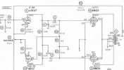
The modified circuits of the 9300 are posted here, with the following notes and features:
POWER SUPPLY:
This remains relatively unchanged except for five basic points:
1. The extra tuner heater winding has now been configured in an autotransformer connection with the primary winding to reduce the voltage applied to the primary winding to 115 vac, which is the design center voltage for this winding. Voltage applied to the heaters is now within 2% of the target value with typical line voltages of 121-122 vac.
2. The hum pot has been eliminated, and balance resistors used in its place. Use of a hum pot in a basic power amplifier setting typically offers little practical advantage.
3. The rectifier tube has been changed to use a 5AR4.
4. The voltage supply points are re-labeled for the correct modified values, which includes a new dedicated output tube screen grid supply point.
5. A 2A fuse and power switch is included for practicality and safety.
Comment: Because this is a development model, the original good can cap is still in place and in use, providing good service. As a result, the 10 uF section originally used to decouple the phase inverter stage is now used to decouple the screen grids, with a new discrete decoupling cap added to decouple the phase inverter stage. Because the screen grid decoupling cap is so small, no Screen Stability resistors were required in the development model, and are not shown in the pic provided. However, they ARE shown on the amplifier page, since any unit destined for regular service will almost certainly have the can cap replaced, with 40-50 uF being a good practical value to use at this point. With such a value, Screen Stability resistors will be required, and are therefore shown on the schematic.
These changes, along with those made to the output stages, now have the power transformer operating at a very cool temperature. After three hours of use in an open 68F environment, the transformer failed to even reach 120F. With typical power transformer operating temps of 140F or so, this sucker is one cool cookie indeed.
AMPLIFIER:
While the basic topology remains the same, important changes have been made that really improves overall performance significantly. These include:
1. OUTPUT STAGE: Operation of the output stage has been modified to use a simplified form of EFB(tm) for pentode operation. In this scenario, no negative fixed bias supply was readily available, so an EFB cathode regulator was used to provide true fixed bias operation. However, with the advantage of the "Enhanced" element that EFB provides, the optimum operating point is always maintained under all conditions of operation, in spite of power supply fluctuations due to AC power and changing dynamic conditions. This is important, as when the amplifier is developing full power into a 4 ohm load in both channels at the same time, the power supply requirements increase from about 90 ma under quiescent conditions, to nearly 200 ma with 15.5 watts RMS being developed in both channels at once. This causes the B+ to the OPTs to drop some 40 vdc -- and importantly, the screen grids by about 50 volts. This would normally produce a significant shift in the operating point, and greatly increase distortion. But because the EFB cathode regulator controls the bias to the tubes -- which is based on the screen grid voltage supplied to the tubes -- the bias is automatically adjusted accordingly, and maintains the optimum operating point regardless of what the B+ voltages are. The only way that this low distortion performance can be matched with traditional absolute regulation, is to regulate ALL grid and plate potentials, which is an expensive proposition to produce. Also, because the loading conditions require the screen grids to operate at nearly the same DC potential as that of the plates, a simple dropping resistor for the screen grids can be used to power them, with little loss of regulation: Of the 50 volts that they drop in operating voltage between quiescent and full power, only 10 of those volts is due to the dropping resistor, which is rather insignificant. Ultimately however, it matters little, since the EFB arrangement accounts for the full drop in screen voltage under large dynamic conditions.
Now besides completely eliminating the notch distortion and greatly reducing THD in general as discussed in the setup posts, the other huge benefit of EFB operation is that the optimum quiescent operating point of the tubes now falls to just 22 ma per tube, or 44 ma per channel. This means that each tube is dissipating just 7 watts at the plate, or less than 60% of the tube's conservative Design Center rating for plate dissipation. This equates to extremely long tube life -- and the cooler power transformer operation. It is also the reason that in spite of the autotransformer connection of the power transformer's primary winding, the lower quiescent current draw and use of a low drop 5AR4 rectifier tube cause the quiescent B+ voltages to rise to higher than normal levels (although the turn on surge is completely eliminated). But this is of little concern, as maximum voltage ratings for vacuum tubes can -- and are -- often exceeded, which can be very safely done -- as long as the tubes are not operating at or near rated dissipation levels. With the very low dissipation levels in this amplifier, the 6BQ5/EL84 output tubes used showed absolutely no signs of concern, and in fact are operating under much less stress than if only 300 volts were applied to the screen and plate elements, but the tubes idled at 35-37 ma each, as is customary in most traditional cathode bias settings. In this amplifier, as the production of power is elevated, the operating voltages will fall as discussed, so that even under full power conditions, the ratings for the tubes are not exceeded. Therefore, the modified design will work just fine with any version of the 6BQ5 family of tubes you wish to use.
End Part 1. Part 2 will be along shortly.



 They were such a nice matched set too . . .
 right now, kinda like walking with a rock in my shoe. Wish I could afford US NOS, but at least cheap matching is better than limping. I see you can get matched quads for pretty reasonable- have you been happy with how they bias up? Any advice is appreciated.