


You are using an out of date browser. It may not display this or other websites correctly.
You should upgrade or use an alternative browser.
You should upgrade or use an alternative browser.
More Fun With Magnavox: The 9300 Series
- Thread starter dcgillespie
- Start date

Lavane
Lunatic Member
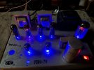
Thanks. Thats the first time I've seen that done to a rectifier.Lavane: here's that pic. Happy Holidays.
Capt Blast
Member
Could probably do it to el34's etc . Anything with a "plastic" 8 pin key I would guess. I was toying with the idea of doing my Dynaco ST-70. If you're going to do it, just make sure you limit the depth of the 1/8 inch drill so when you punch through it stops before hitting the glass!!. I used a piece of brass tubing that left about 1/8 inch of drill tip sticking out. I found you can hook up a pair of blue leds in series with a 100 Ohm resistor right off the 6.3v heater and they are still pretty bright. I'm sure somebody here can recommend the "right" resistor as I just shot from the hip and experimented. To limit an imbalance in the heater circuit and possible hum, I tried to make the pairs be alternated such that as close to half of them used one side of the 6.3v as the "start" and the other half used the other side as the start. My heater voltage was a little high anyway so the LED current draw was directionally OK, even tho its pretty nominal. If you use green LEDs, does it make your Magnavox a McIntosh? 
 Red for the rectifier, and another color for the rest maybe.
Capt Blast
Member
That could be cool. Just remember different colored LED's use more or less current so the size of the resistor will be different. I just realized I'm running vintage real Mullard EL34's in my Dynaco ST 70. Ain't drillin' no enlarged holes in those. 




petrnyc
Active Member
Anyone…. Somebody… ? ? ?Hello,
Anyone in NYC area I need to test couple el84 pp amps for proper feedback values for the caps and resistors with Output transformers that are not the specified ones to the build schematic, and don't have the machinery to do it, able to pay.
Thanks

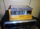
Sooo- This thread is so long and old it's maybe inconsequential to post to it, but I had to relate to it's participants how happy I am that Mr. Gillespie took the painstaking efforts and time to redesign the 9300 into something really quite respectable, and how much this has meant to me and my journey in this hobby. I very much wish that Audiokarma had a library of technical articles, as Dave's modifications to the design of this chassis are worth much more than being lost in the belly of a mile long thread. I hope (and maybe he has?) Dave would publish this online or something. (Please tell me if he has.)
I found my 9302 in the belly of a dusty $40 console at a local thrift store. I knew nothing about the chassis I could barely make out through the ventilation holes, only that it had tubes and looked like it would be an excellent candidate for a stand-alone amp. I put it through it's paces while completely stock (after a good clean-up and tube testing and slow-bring-up, etc) and found it very wanting. Lucky Magnavox had those thick and velvety vailed speakers to obscure all of the shortcomings- the sound was thin, grating and fatiguing, and as Dave mentioned it was not at all suited to be a stand alone audiophile component. Imagine my joy when I found Dave's modifications and the great long discussions here on Audiokarma, and the work on these that so many others had done. I immediately became a member and have really enjoyed reading the forums. I'm a retired electrical engineer who has previously collected and restored antique tube radios, so I understand tube theory and circuit functionality, but have never studied amplifier design so this was a new chapter for me.
My desire for this amplifier was to (as Dave did initially) improve the performance as much as possible while staying within the confines of the original platform. As with a classic car, no bolt-on spoilers or fender flairs or ground effects for me- honor the appearance of the chassis as much as possible, let it be what it is, but some cosmetic deletes and performance modifications "under the hood" are fair game! I opted for Dave's "stage 1" mods, everthing up to replacing the output transformers or adding an extra tube. I figure if you really want bigger output transformers and move to that elite class it's probably more attractive and practical to start with a blank chassis.
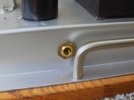
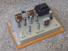
I love the original ink-stamped chassis numbers, and took care to preserve them when I wiped the whole chassis down with vinegar to remove the toxic green cadmium corrosion inside and out. I removed the ugly can capacitor, hum and balance pots, pilot and speaker phenolic connectors, and filled all of the holes. I found that the thinner sheet metal from the scrapped radio chassis shielding was perfect patch material with the exact cadmium plating as the amp chassis. Fortunately I have a 200W soldering gun that made tacking the patches and adding extra terminal strips super easy. I liked the original input placement, but the cheesy phenolic connector with super tight spacing had to go and was replaced as shown. I really don't like the huge red and black speaker terminals, so opted for the really understated banana jacks that fit right behind the transformers. I mounted a fender bias pot (screwdriver adjust) in the side hole where the cord originally came in, and hid three pin jacks behind the power transformer to stick my meter probes when making the bias adjustment. I have been calling it my "little milk-crate amp". I wanted to mount it on a slab aged and distressed yellow pine, but opted for this piece of oak I cut down from an old cabinet door. The drawer pull handles at the center of gravity are again intentionally understated, but make moving this thing around a lot easier.
I added a simplistic voltage divider volume control at the inputs so I could connect a source directly to it and set an unobtrusive volume knob down in the extra tube hole. I used a 10K pot to minimize the high frequency loss at lower volume levels as Dave warned about, and find that it incurres little frequency degradation, at least to my ears. When I use my pre-amp it will be at maximum and have no impact anyway. I found all of Dave's instructions very clear and easy to follow, and much thanks for the excellent schematic and writeup. It took me about three days total to neatly perform all of the modifications, and enjoyed every mintute of it. I'd like to post a picture from under the chassis at some point, I was so excited in testing and completing it I forgot to take the pictures. Adjusting the bias is a cinch. I was amazed at how very different the bias current was for various tubes. I found Dave's suggestion of using the bias measurement to match tubes very helpful- Dial in one "reference" tube (to .22V) , and measure others at the same setting. I was able to quickly find a set out of my stash that were close enough from at least a bias perspective so the two sides were relatively equal.
The final result is AMAZING to listen to. Very clean- no hint of the previous distortion. Transparent, flat from horizon to horizon, no noise, amazing detail, has that amazingly vibrant yummy tube goodness =AND= manages to hold it together as I crank it up. The difference from stock is night and day. Thank you, Dave, for your gift to the world. Keep it up.
Anyway, sorry for rambling, mad props to Mr. Gillespie, and I hope you enjoy the outcome. -Warren
I found my 9302 in the belly of a dusty $40 console at a local thrift store. I knew nothing about the chassis I could barely make out through the ventilation holes, only that it had tubes and looked like it would be an excellent candidate for a stand-alone amp. I put it through it's paces while completely stock (after a good clean-up and tube testing and slow-bring-up, etc) and found it very wanting. Lucky Magnavox had those thick and velvety vailed speakers to obscure all of the shortcomings- the sound was thin, grating and fatiguing, and as Dave mentioned it was not at all suited to be a stand alone audiophile component. Imagine my joy when I found Dave's modifications and the great long discussions here on Audiokarma, and the work on these that so many others had done. I immediately became a member and have really enjoyed reading the forums. I'm a retired electrical engineer who has previously collected and restored antique tube radios, so I understand tube theory and circuit functionality, but have never studied amplifier design so this was a new chapter for me.
My desire for this amplifier was to (as Dave did initially) improve the performance as much as possible while staying within the confines of the original platform. As with a classic car, no bolt-on spoilers or fender flairs or ground effects for me- honor the appearance of the chassis as much as possible, let it be what it is, but some cosmetic deletes and performance modifications "under the hood" are fair game! I opted for Dave's "stage 1" mods, everthing up to replacing the output transformers or adding an extra tube. I figure if you really want bigger output transformers and move to that elite class it's probably more attractive and practical to start with a blank chassis.
I love the original ink-stamped chassis numbers, and took care to preserve them when I wiped the whole chassis down with vinegar to remove the toxic green cadmium corrosion inside and out. I removed the ugly can capacitor, hum and balance pots, pilot and speaker phenolic connectors, and filled all of the holes. I found that the thinner sheet metal from the scrapped radio chassis shielding was perfect patch material with the exact cadmium plating as the amp chassis. Fortunately I have a 200W soldering gun that made tacking the patches and adding extra terminal strips super easy. I liked the original input placement, but the cheesy phenolic connector with super tight spacing had to go and was replaced as shown. I really don't like the huge red and black speaker terminals, so opted for the really understated banana jacks that fit right behind the transformers. I mounted a fender bias pot (screwdriver adjust) in the side hole where the cord originally came in, and hid three pin jacks behind the power transformer to stick my meter probes when making the bias adjustment. I have been calling it my "little milk-crate amp". I wanted to mount it on a slab aged and distressed yellow pine, but opted for this piece of oak I cut down from an old cabinet door. The drawer pull handles at the center of gravity are again intentionally understated, but make moving this thing around a lot easier.
I added a simplistic voltage divider volume control at the inputs so I could connect a source directly to it and set an unobtrusive volume knob down in the extra tube hole. I used a 10K pot to minimize the high frequency loss at lower volume levels as Dave warned about, and find that it incurres little frequency degradation, at least to my ears. When I use my pre-amp it will be at maximum and have no impact anyway. I found all of Dave's instructions very clear and easy to follow, and much thanks for the excellent schematic and writeup. It took me about three days total to neatly perform all of the modifications, and enjoyed every mintute of it. I'd like to post a picture from under the chassis at some point, I was so excited in testing and completing it I forgot to take the pictures. Adjusting the bias is a cinch. I was amazed at how very different the bias current was for various tubes. I found Dave's suggestion of using the bias measurement to match tubes very helpful- Dial in one "reference" tube (to .22V) , and measure others at the same setting. I was able to quickly find a set out of my stash that were close enough from at least a bias perspective so the two sides were relatively equal.
The final result is AMAZING to listen to. Very clean- no hint of the previous distortion. Transparent, flat from horizon to horizon, no noise, amazing detail, has that amazingly vibrant yummy tube goodness =AND= manages to hold it together as I crank it up. The difference from stock is night and day. Thank you, Dave, for your gift to the world. Keep it up.
Anyway, sorry for rambling, mad props to Mr. Gillespie, and I hope you enjoy the outcome. -Warren
Attachments



wparks -- Thanks for the very kind words!
This whole Magnavox "thing" started as a SE 6BQ5 8600 series project to do with a grandson. It turned out so unbelievably well that I thought I would casually share it in case others were looking for a good project to get into this hobby with, while also learning some basic concepts along the way and getting their hands wet in doing so. The response to that project has been unbelievably over the top beyond my wildest imagination, and ultimately morphed into this thread for the 9300 series, and then finally into the thread for the 6V6 8800 series. All of these Magnavox projects have returned a satisfaction level that lies in that wonderful realm of returning way more than the sum of their parts would ever suggest.
I'm so glad your 9300 series returned that same level of satisfaction for you -- not only through enjoying the final product it produces musically, but in your own journey of learning and working with these circuits, and the personal satisfaction that returns as well. It sounds like you are fully addicted now!
Congrats on success of your project and thanks for sharing it with the AK Community!
Dave
This whole Magnavox "thing" started as a SE 6BQ5 8600 series project to do with a grandson. It turned out so unbelievably well that I thought I would casually share it in case others were looking for a good project to get into this hobby with, while also learning some basic concepts along the way and getting their hands wet in doing so. The response to that project has been unbelievably over the top beyond my wildest imagination, and ultimately morphed into this thread for the 9300 series, and then finally into the thread for the 6V6 8800 series. All of these Magnavox projects have returned a satisfaction level that lies in that wonderful realm of returning way more than the sum of their parts would ever suggest.
I'm so glad your 9300 series returned that same level of satisfaction for you -- not only through enjoying the final product it produces musically, but in your own journey of learning and working with these circuits, and the personal satisfaction that returns as well. It sounds like you are fully addicted now!
Congrats on success of your project and thanks for sharing it with the AK Community!
Dave

I’ve been waiting for a Maggie 8600 to rebuild (Dave’s Flea Power project) for a while, but despite many Magnavox consoles coming up near me on FB Marketplace, they are mostly solid-state or the beloved is too expensive. Then yesterday, an Italian Provincial (yuck!) console came up 10 miles away but not much info or pictures. It was $50 and being sold by a moving company. I inquired to see if they could pull the back off and send some pics. Pics come back and to my delight, I see 9302 and lots of tubes, made in Great Brittain tubes! Sold. Then I wondered how much information is on AK about refurbing a Maggie 9302, and there it is 75 pages of Dave Gillespie joy. So I’m off on my next project.
Output tube codes are rX1 (EL84 first production), and B1 (Mullard, Blackburn Works, 1961) dates Feb, May, May & July. The 6EU7s are first production, also Blackburn 1961 dates Apr & May. The rectifier tube is Sylvania Oct 1961.
Output tube codes are rX1 (EL84 first production), and B1 (Mullard, Blackburn Works, 1961) dates Feb, May, May & July. The 6EU7s are first production, also Blackburn 1961 dates Apr & May. The rectifier tube is Sylvania Oct 1961.
Attachments
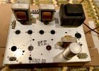

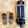

Maybe someone who's been following this all along can tell me: Other than the original two schematics (amp and power supply) Dave posted on Pg 4 of this thread, were there ever any 'updated' revisions posted, or was that really the final product? Yes, I could read all 75 pages, and if that's what it takes, that's what I'll do!! But, as I just found one of these tucked at the back corner of one of my storage shelves, I'm thinking I might just drop all my other projects and go about doing the DG version to the unit I found. I did go through the first 10 pages of this thread again, and I didn't see any changes up to that point, but, with 65 more to go, wouldn't surprise me in the least if a change or two to the original drawing had come out of 'Dave's Lab'!! Thx, Tom
Lavane
Lunatic Member
Nice score. They do sound good. The console I found out back of a thrift store that was left out in the weather came with Mullard EL84's and 6EU7's.I’ve been waiting for a Maggie 8600 to rebuild (Dave’s Flea Power project) for a while, but despite many Magnavox consoles coming up near me on FB Marketplace, they are mostly solid-state or the beloved is too expensive. Then yesterday, an Italian Provincial (yuck!) console came up 10 miles away but not much info or pictures. It was $50 and being sold by a moving company. I inquired to see if they could pull the back off and send some pics. Pics come back and to my delight, I see 9302 and lots of tubes, made in Great Brittain tubes! Sold. Then I wondered how much information is on AK about refurbing a Maggie 9302, and there it is 75 pages of Dave Gillespie joy. So I’m off on my next project.
Output tube codes are rX1 (EL84 first production), and B1 (Mullard, Blackburn Works, 1961) dates Feb, May, May & July. The 6EU7s are first production, also Blackburn 1961 dates Apr & May. The rectifier tube is Sylvania Oct 1961.
I still have two of the Mullards in a single ended amp. One of the four lost vacume.
I hate it when that happens! I can't count how many 9-pin tubes I've llost to either a broken off twist-seal at the top of the tube, or a fracture by a pin at the bottom!!
Why can't I find a nice amplifier on the side of the road????
Why can't I find a nice amplifier on the side of the road????

Other than the original two schematics (amp and power supply) Dave posted on Pg 4 of this thread, were there ever any 'updated' revisions posted, or was that really the final product
somewhere a little further on is a hybrid schematic, the original one Dave posted with stock transformers plus the cathode follower from the later one with the Dyna iron. I think I actually posted it, its fairly crudely spliced together from his two drawings.

Dswankey
Lunatic Member
@Wharfcreek
I'm not sure if these are the ones you're looking for
schem's
on page 20 (post #385)
on page 21 (post #401 by gadget)
^Post 1,285
I'm not sure if these are the ones you're looking for
schem's
on page 20 (post #385)
on page 21 (post #401 by gadget)
^Post 1,285
Last edited: