• The move to the new server is done. There are some software and database maintenance updates in process. This has us passing the hat around to help out. We appreciate any donations. Seriously, even a dollar helps. The payment page may be found here - https://www.audiokarma.org/support.html

More Fun With Magnavox: The 9300 Series

Gadget,
I'm still having trouble wrapping my head around the bias circuit/two channels. I assumed there was only one bias pot and associated circuit because (1) author Gillespie calls for a matched quad of 6BQ5s, with each pair of cathodes going to the LM337 via the 10 ohm resistors. Plus I'm only seeing one bias pot and its associated circuitry in author Gillespie's gut shot. Don't know why but I can't get my head around this one!
SAM_1608.jpeg
 
There is only one bias pot, it adjusts all 4 tubes at the same time. Output of the LM337 goes to the middle terminal on the strip mounted between the rectifier and output tubes. You can see the two 10 ohm resistors land there, and their opposite ends go to the ends of the terminal strips. One of those ties to the left pair of tubes, the other to the right pair of tubes.


essentially the LM337 is replacing the original single cathode bias resistor that handled all 4 tubes.
 
Thanks! That's what it looked like to me, but I was not sure.
It just threw me off earlier when you wrote: "build what you see on the page twice except for the LM337."
Thanks for the clarification.
 
It does help, confirms just one bias pot as I had thought. So, the only thing that I'm building in the other channel is the connection to the LM337, as well as a connection to the 370V line? I thought that was the case, as it didn't make any sense to me at all to have two different bias pots and associated circuitry, both connected to the 370V line ...

By the way, fantastic lead dress.
 
Here's another question I hadn't thought of earlier.
To recap, I'm building this circuit from scratch.
The power transformer I am using came off a junker Pilot 602 4x6BQ5 receiver. I'm wondering about the feed from the center tap of the 6.3v filament winding to the LM337. On my transformer, there are THREE 2.5A 6.3v windings. Each powered one channel plus phase inverter, AF, etc., and the third powered radio tubes.

The 3.15vac or so coming from the 6.3vac artificial center tap (220 ohm resistors junction) .... Am I OK to run this to just one of the 6.3V windings? I'm assuming its to just supply small AC voltage that's then rectified by the LM337 and send to the 6BQ5s...

Thank you.
 
you can run it to both of the windings if you are doing one per channel. The third winding maybe can be used as a bucking winding if the heater supply voltages come out too high.

the purpose is to put some positive DC voltage on the heater string. It helps reduce noise pickup. The resistors just balance it across both sides of the winding.
 
Thanks, that's good to know.
I have seen elevated center taps before, but always in cathode biased tube amps, and when I build guitar amps I usually elevate the center tap to cut down on noise. I've just never seen it in this kind of biasing setup.
I was definitely toying with using that third winding to buck the primary winding. At 2.5A it should be fine in that role!
Thanks.
 
In stock form, the 9300 used a single resistor and the cathodes were tied to the hum balance pot. Still doing the same thing, just the resistor has been replaced with a silicon part.
 
Hi all, a couple years ago I rebuilt the amp in my Magavox console per the advice and here and all is well. I'm still running the tuner, etc and keeping the console together. I recently fixed the turntable and now everything is working pretty well. The frequency response is certainly "off", but probably within the bounds of what's to be expected from this setup.

I'm curios about the wiring of the speakers and replacing the crossover capacitor. It appears the big side-firing speakers are wired in parallel with the two "tweeters" that are together in series along with the capacitor. It seems to be a 16mfd. Can you all confirm this wiring scheme? What would you recommend replacing the capacitor with? I don't need anything fancy, just functional. Thanks
 
sounds about right. The cap is a simple "bass blocker" setup. The 12" run full range. Thats actually part of where the frequency response funkiness comes from, its got a lot of overlap in the midrange and those tweeters don't go way up either.

anyway, 16uf non-polar electrolytic would do the job just fine. If that value doesn't exist, 15uf and a 1uf in parallel would do it.

if you want to get more fancy with it you could design a real crossover so the 12" only goes up so far, the tweeters run as a midrange, and add an actual tweeter to make the top end really work. I kind-of did that with my Hoffman console, using a 3 way salvaged from some Polk speakers and adding a little Vifa dome tweeter. Its far from perfect but a lot better.
 
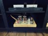
Here is my recently completed 9300 series based on Dave Gillespie's design with the stock output transformers and EFB. This amp sounds wonderful and I like it more than my 8600 series DG-SE1. This may be partly due to the higher output power of the 9300 through my 87 db speakers. Anyway my question is if you look at my picture I am using a DVD player through a Schitt Modi 3 DAC to a Schitt SYS for the volume control. Like I said it sounds great but I was wondering if I should be using the input sensitivity reduction network shown on the schematic or maybe even the buffer shown on the schematic for the Z-565 output transformers.
Howard
 

Attachments

  • IMG_20230228_205952.jpg
    IMG_20230228_205952.jpg
    72.5 KB · Views: 56
the buffer is nice especially if you want to add a volume control. No HF loss as the volume is adjusted. If you have an external control I'd say its probably not needed. If the external control is overly sensitive though, the sensitivity reduction network would be a good idea.
 
G
the buffer is nice especially if you want to add a volume control. No HF loss as the volume is adjusted. If you have an external control I'd say its probably not needed. If the external control is overly sensitive though, the sensitivity reduction network would be a good idea.
Gadget, thanks for the response. I don't notice any sensitivity problems, is this something that has to be measured? I think I will go ahead and add the buffer.
 
If all of your useful volume control is in the first small fraction of rotation and its just annoyingly touchy, its too sensitive. If you have no issues its fine.
 
Not much to do with the attenuator, it's more about source output level vs input sensitivity. If the source cranks out a lot more than what the amp wants for full output power at most you can use only a small part of the signal and that tends to put the useful travel of the volume pot to a small range. I have a Pioneer designed like that and its obnoxious. No volume is 7:00 and as loud as I want to hear it is 9:00. Breathe on the thing and it's a big change.

I mean functionally it works, but personally I find it annoying. My opinion and 5 bucks buys a coffee though so take it for what its worth :)
 
Back
Top Bottom