• The move to the new server is done. There are some software and database maintenance updates in process. This has us passing the hat around to help out. We appreciate any donations. Seriously, even a dollar helps. The payment page may be found here - https://www.audiokarma.org/support.html

More Fun With Magnavox: The 9300 Series

With both end bells above the chassis and with more length or width than height, these have always been referred to as 'lay-down' vs 'stand-up' types from what I've been led to understand. Maybe just a disparity in definition, but either being different from a 'thru-mount' where the big hole is needed and half the winding ends up under the chassis.
 
I posted those transformers because all the ones mentioned in this discussion are virtually unobtainable. And the Dynaco ones that Dave has done the research and troubleshooting for are really impossible to get. A set on Ebay, but no testing data with a no return policy. The impression I got reading through all 75 pages is that the stock transformer gets you 90% of the way, Dave never intended to make this a luxury dreamboat mod, just an impressive improvement.
Without the know how and test gear to get a fresh set of transformers to operate to their best level leads you back to staying stock and use the Nov 2015 schematic. That's where I am.
 
I modified my design some time back to Dave's "original" upgrade, and am going to be upgrading it again to the "newer" upgrade. I'm curious what the buffer tube actually does though. As in, technically. Why does it benefit this design? I have to admit that I didn't read the entire 75 pages of this thread, but I never did see a real explanation of WHY the buffer benefits this amp. Just that it does. Is it an impedance thing or is it about gain? Neither?
 
The buffer lets you stick a volume control in front of it with no HF roll-off issues. Thats the practical benefit that most people would see.
 
Time for me to bump this epic, epic thread! I'm going to confess to not having read all 80-ish pages, but I did search for my odd topics and didn't find any direct answers.

I am probably the only person who's going to perform Dave's mods and then leave the amp in the console, so I really don't care what it looks like. I'm also probably the only person who's in Europe and going to be using this on 230V 50Hz power. My plan is to shine up the very good condition Danish Modern cabinet, modify the amp, modify the tuner/preamp, modify the speakers (which really sound terrible), and have something that will keep up with modern music and sources. The situation does leave a couple of questions though:

- I'll be using an autoformer to drop the 230V down to about 117V, and of course I'll have the tuner/preamp connected which will lower the output of the power transformer a bit more. Is there any reason I can't just put a couple of 1N4007s in place of the rectifier tube? I'd use a thermistor before the choke to dribble out the B+ until things warm up. I plan to slightly increase the value of the filters post-choke in order to compensate for the 50Hz power, even though in stock form there isn't excessive ripple with the original can. Just doing a test tacking in a couple of diodes I'm getting 380V B+, which seems like it is close enough.
- Any opinions about using 6π14πs instead of 6BQ5s? I think these should just swap straight across, no? I can get matched quads for about 15 bucks, so...
- I saw someone refer to the cap labeled "390" on the plate of the first stage as "390pf" - this should be 390nf, correct?
- I can't find an LM337A anywhere in Europe. All I can get is an LM337T, which seems to be the same. Any reason I can't use that?

Any other advice for my particular weird use case? I've got questions about the mods I want to do to the preamp and speakers, but I'll start another thread for those.

Thanks everyone!

 
The buffer is a good upgrade if you need it. I tried putting it in and found that my layout skills were not up to the task- ran into difficulty getting it to fit without looking like a phone pole in Thailand. View attachment 2619853
I'm amazed there aren't any real birds nests in that jumble of cable.
I bet the roof rats get lost navigating that mess. :D
 
- I'll be using an autoformer to drop the 230V down to about 117V, and of course I'll have the tuner/preamp connected which will lower the output of the power transformer a bit more. Is there any reason I can't just put a couple of 1N4007s in place of the rectifier tube? I'd use a thermistor before the choke to dribble out the B+ until things warm up. I plan to slightly increase the value of the filters post-choke in order to compensate for the 50Hz power, even though in stock form there isn't excessive ripple with the original can. Just doing a test tacking in a couple of diodes I'm getting 380V B+, which seems like it is close enough.
- Any opinions about using 6π14πs instead of 6BQ5s? I think these should just swap straight across, no? I can get matched quads for about 15 bucks, so...
- I saw someone refer to the cap labeled "390" on the plate of the first stage as "390pf" - this should be 390nf, correct?
- I can't find an LM337A anywhere in Europe. All I can get is an LM337T, which seems to be the same. Any reason I can't use that?

Any other advice for my particular weird use case? I've got questions about the mods I want to do to the preamp and speakers, but I'll start another thread for those.

Thanks everyone!

You can, but the voltage and peak current load on the transformer will be higher. If you add a resistor in there, probably in the 50 ohm at 10 watts range between the diodes and the first cap it should simulate the tube rectifier. Adjust as needed to fix the voltage. May have to play with some of the other power supply resistors to allow for the extra load of the tuner. Not a big deal, just some of the resistors will probably end up smaller.

6p14p will work fine

390 picofarad is correct. 390nf would absolutely murder the HF response.

Should be fine.
 
Thanks very much for the response. I'll give it a try with a 47Ω 10W I have lying around and see how that does. 390pf also. This is gonna be a fun project!

ETA: those 390pf caps are hard to come by - either I can get one rated at 100V tomorrow, get a 500V one on a slow boat from China in the next month or two, or order from Mouser/Farnell/Digikey and pay $30 in shipping for two 25-cent capacitors. I wonder if the 100V would be enough eith that resistor in series?
 
Last edited:
probably not, its going to see plate voltage of the tube plus the AC, so 185 plus whatever the AC is. At a minimum I'd say a 250v cap.

can you make 390pf with some more available caps in parallel? Those caps should have at least a 5% tolerance so you could probably get away with 370 - 410pf.
 
FWIW, after doing the full Gillespie mods I tried using a couple different quads of eBay 6p14p's. I was having trouble getting full bias and thought I had done something wrong. I then tried a quad of Sovtek 6bq5's and it biased up perfectly right in about the middle range of the adjustment pot.

Never did figure out what was up because all the 6p14p's tested good on my Sencore MU150 tester?
 
Hey 'nothing quick question about this circuit: the two resistors that took the place of the hum balance pot have their junction labeled on the PS schematic "to output of LM337" - is that supposed to connect right to the output terminal of the regulator? Asking because it isn't mentioned on the amp schematic.
 
Hey 'nothing quick question about this circuit: the two resistors that took the place of the hum balance pot have their junction labeled on the PS schematic "to output of LM337" - is that supposed to connect right to the output terminal of the regulator? Asking because it isn't mentioned on the amp schematic.
Does this help? You can see the two resistors attached to the tube heater circuits.IMG_20221113_115612507.jpg
 
Mine is still tied to the cathodes, but that is also the output of the LM337. Doesn't make any real difference which side of the 10 ohm resistor it connects to.
 
FWIW, after doing the full Gillespie mods I tried using a couple different quads of eBay 6p14p's. I was having trouble getting full bias and thought I had done something wrong. I then tried a quad of Sovtek 6bq5's and it biased up perfectly right in about the middle range of the adjustment pot.

Never did figure out what was up because all the 6p14p's tested good on my Sencore MU150 tester?
I recently ordered a quad of Reflector 6P14P-K's. I'll have to check the bias once they arrive and I try them. I don't have EFB in mine though, just split cathodes.
 
Hi all, I'm very late to the party on this incredible thread. However, I'm going to start building the first version (referenced on page 4 of this thread) soon. I have two questions and wonder if anyone can shed some light.

1. First, referring to the schematic, the output stage obviously has the biasing circuit, with an arrow "to other channel" that would connect to a 10 ohm resistor tied to the cathodes of that other channel. My question is, what is the schematic for that other channel? Should I leave out the entire biasing circuit on that channel, and just connect those cathodes to the 10 ohm resistor and then on to the LM337? Then the only thing else I would need to have on that other channel would be the 370V B+ feed shown in the schematic?
2. I'm curious about adding a balance pot. There is one in the original 9302, but it appears to have been taken out in Dave's version. Any thoughts on how to incorporate one?

Thank you! I also want to thank Dave Gillespie for his amazing work, I can't wait to start. dcmag1.jpeg
 
1) build what you see on the page twice except for the LM337. The second channel is identical, but its fairly common practice to just draw one channel rather than duplicate the work and eat a lot of paper space.

2) Which balance pot? There are possibly two. One is a hum balance that goes across the heater circuit, the other is in the feedback circuit that messes with channel balance. The hum balance is taken care of with the two resistors across the heater supply (the power supply schematic is a seperate page, in this thread somewhere) and the channel balance as-designed is quite frankly a bad idea. Honestly if you need a channel balance pot, that would best be done in the preamp.
 
Thanks. OK on the schematic; reading the thread I thought I only saw one bias pot.

also, sorry I was talking about channel balance.
i am building from scratch, but adding volume control and a simple 12a?7 preamp gain stage, one triode per channel so it’ll be more an integrated amp and won’t need a preamp. That’s why I was looking to do a balance. Thanks,

Ted
 
Last edited:
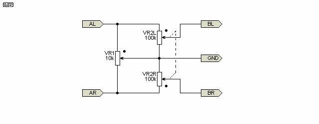
something like this would make for a better balance control

p88-f3.gif


can also flip the position of the balance control to be after the volume control, though I'd probably go with something like a 250k-500k pot if you put it there. Those values are also just what was on the schematic, can use higher if you like or need a higher input impedance.
Fantastic, thanks. I’ll fiddle around with this. Thanks for passing on this schematic
 
Back
Top Bottom