• The move to the new server is done. There are some software and database maintenance updates in process. This has us passing the hat around to help out. We appreciate any donations. Seriously, even a dollar helps. The payment page may be found here - https://www.audiokarma.org/support.html

Magnavox 9304 (el84) - sounds flat/muffled/blah - help!

Scott Shular

New Member
Hello all, hoping to find some direction here.

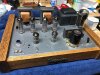
I have a Magnavox 9304 stand alone amp. The amp sounds flat, maybe even a little 'muffled' sounding. Most recently have it paired with an Advent 300 preamped out , speakers were Large Advents and tried KHL Model 17's.
For comparison, the Advent 300 on its own sounded pretty damn fine!

Few notes:
I have tried two different sets of EL84 power tubes and 6EU7 and 12AX7 pre tubes (i have an adapter).

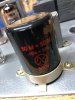
I had replaced all the caps including the can cap.

I have tried a few different coupling cap combinations, currently .1 and .01

I have started to check on some of the resistors which are mostly original. I have noticed several out of spec (over) which is what I read will indicate a failed resistor. -- - Can resistors affect the sound to what I'm describing?

Lastly, I'm no pro. Intermediate who does a lot of research before he makes any changes...not that all advice online is good advice...

Any advice however is very welcome!

Thanks all!
 

Attachments

  • IMG_2732.jpg
    IMG_2732.jpg
    166.1 KB · Views: 57
  • IMG_2733.jpg
    IMG_2733.jpg
    122.9 KB · Views: 54
  • IMG_2734.jpg
    IMG_2734.jpg
    172.8 KB · Views: 53
  • IMG_2738.jpg
    IMG_2738.jpg
    97.6 KB · Views: 53
  • IMG_2739.jpg
    IMG_2739.jpg
    170.8 KB · Views: 52
Register to hide this ad
stock circuit or something else?

Off value resistors aren't going to help. How are the voltages on the output and 6EU7 tubes compared to the schematic?

these are capable of much better than stock circuit performance if you're up for some re-work. The thread is long and gets veered off topic a bit but there is a ton of good info here.

https://audiokarma.org/forums/index.php?threads/more-fun-with-magnavox-the-9300-series.687735/

More Fun With Magnavox: The 9300 Series

is a direct link to the post with the schematic but the first few posts that analyze the stock circuit are worth a read even if you skip much of the stuff in the middle.
 
Thanks gadget73. I'll have to do a little research on checking the voltages, I have lots of schematics etc at home. I'd imagine I need to identify the right pin? Are we talking plate voltage? Again, no pro but I like learning...
 
plate and cathode ideally. On the 6eu7 cathodes are 4 and 5, plates are 6 and 7. The other important resistors are the 6bq5 grid resistors. One side has a 470k and I think a 33k? (can't read it) and the other one is 220k. The side with two resistors, both of those need to be somewhere fairly close to the right value or the phase inverter balance goes out the window.

One of the assorted faults Dave's re-work fixes is the tendency for poor inverter balance.
 
I have tried a few different coupling cap combinations, currently .1 and .01

I have started to check on some of the resistors which are mostly original. I have noticed several out of spec (over) which is what I read will indicate a failed resistor. -- - Can resistors affect the sound to what I'm describing?
Welcome to AK!

Not sure if it would produce a "muffled" sound, but you're using coupling caps that are twice the value of the original. This will send more bass frequencies to the output transformers (OTs) and they may not be able to handle it. The OTs used in most console amps are pretty small and they may become saturated if you try to ask too much of them.

The carbon comp resistors tend to drift high over time. Since these amps really don't have that many of them I'd suggest that you just replace them all. I typically use carbon films.

The coupling cap and the grid leak resistor that follows it combine to produce a high pass filter which allows higher frequencies to pass and rolls off the lows. With a 0.1uf cap and a 470k resistor, as in your amp, the -3db point is only ~3.4hz. The stock .047 cap produces a -3db point of ~7.2hz. And, if your resistors are out of spec and measure high, that will drop the -3db frequency even lower.

I've had good results going the other direction, using a smaller value coupling cap and moving the -3db point a bit higher. This takes some of the strain off of the small OTs.

For example, if you use a .022 coupling cap and a 470k grid leak resistor, the -3db point will be ~15.4hz. A .033 cap will yield a -3db point of ~10.3hz.

Depending on what type of music you listen to and the speakers you use, raising the -3db point a bit is usually not an issue. In most modern music the lowest frequency instrument is often the bass (guitar or upright). The lowest frequency on a 4 string bass is the open E string, which is just over 40hz. The next highest string, the open A, is 55hz. There are only 5 notes on the bass that are lower than 55hz. On most songs, 90% or more of the bass notes are 55hz or higher. On a 5 string bass the lowest note is an open B string, which is just over 31hz.

Obviously, if you listen to pipe organ music or genres which employ very low frequencies as special effects, YMMV.

It's very possible that your speakers won't even reproduce really low frequencies with any authority. An online tone generator will allow you the find out the limits of the combination of your speakers and your ears.

I figure there's no point in stressing the OTs trying to get them to reproduce frequencies that are inaudible. And you can always add a powered subwoofer if the lowest frequencies are missing.

Thanks gadget73. I'll have to do a little research on checking the voltages, I have lots of schematics etc at home. I'd imagine I need to identify the right pin? Are we talking plate voltage? Again, no pro but I like learning...
You rebuilt the amp but never checked any voltages? You won't be able to tell if the amp is operating correctly unless you've checked voltages.
 
Thanks all, learning a lot, had a chance to tool around this morning....

Took some voltages. This was with the Coupling Caps you see in my pics - .1uf/.01uf. Probably a good time to ask, are those both consider 'coupling caps' or are the smaller ones 'bypass' Thanks for your patience!

6EU7's Left Right Per 9300 schematic spec

Pin 4 (Cathode) 2.33 2.28 1.9v
Pin 9 (Cathode) 1.79 1.78 1.3v
Pin 6 (Plate) 167 193 160v
Pin 7 (Plate) 168 185 130v

6BQ5's Left 1 Left 2 Right 1 Right 2
Pin 7 (plate) 307 310 310 308
Pin 9 (Grid/Screen) 313 313 313 313

Then, I swapped out the .1uf coupling cap per Flacharlie and replaced with a .047. So now I have .047uf/ .01uf Hooked it up and gotta say I hear an improvement. Enough so that I played side one of Moving Pictures since Tom Sawyer is one of my benchmarks when I listen.

So any thoughts on above? Concerns. Considering how cheap resistors are do I do a wholesale change on these?

Thanks all!
 
Ugh! My specs did not post as I typed them (in columns).

The 6EU7's have 3 voltages listed for each one, the left tube, the right tube and what the schematics says I'm looking for. Similar for the 6BQ5's
 
you're in the neighborhood, Everything being a bit high is typical with higher line voltages and no tuner load, especially if you aren't using the extra heater winding as a bucking winding. Right side plate voltages are more off than I'd expect but that could be a tube thing. If you swap them and the voltages follow, its just differences in condition. I don't see anything completely off the rails though.


The caps between the 6eu7 and the 6bq5 are coupling. Ones going to ground are bypass.

resistors are cheap and easy. won't hurt. Dave's re-work will take it a lot further though. More power output and much improved frequency response. Even if you don't do the EFB part, the re-work of the phase inverter and the HF tuning for the feedback network should help.
 
Thanks all, learning a lot, had a chance to tool around this morning....

Took some voltages. This was with the Coupling Caps you see in my pics - .1uf/.01uf. Probably a good time to ask, are those both consider 'coupling caps' or are the smaller ones 'bypass' Thanks for your patience!

6EU7's Left Right Per 9300 schematic spec

Pin 4 (Cathode) 2.33 2.28 1.9v
Pin 9 (Cathode) 1.79 1.78 1.3v
Pin 6 (Plate) 167 193 160v
Pin 7 (Plate) 168 185 130v

6BQ5's Left 1 Left 2 Right 1 Right 2
Pin 7 (plate) 307 310 310 308
Pin 9 (Grid/Screen) 313 313 313 313

Then, I swapped out the .1uf coupling cap per Flacharlie and replaced with a .047. So now I have .047uf/ .01uf Hooked it up and gotta say I hear an improvement. Enough so that I played side one of Moving Pictures since Tom Sawyer is one of my benchmarks when I listen.

So any thoughts on above? Concerns. Considering how cheap resistors are do I do a wholesale change on these?

Thanks all!
The caps are all considered "coupling caps". The paraphase inverter uses different values like that. I don't understand the technical reasons but I'm sure someone can explain.

The original values are .047 and .0047, so you need to change the others to get back to the original. At this point you're halfway back.

You should read through Dave's mod thread on these amps and consider making some changes. The links were posted earlier. While I haven't done his mods, I'm sure they are a big improvement. One thing he does is switch from the stock paraphase inverter to a "floating paraphase".

Yeah, since there aren't that many resistors and these old carbon comps are likely out of spec, I'd just replace them all. I typically use carbon films. Re-check voltages after you put in new resistors and see where you stand.

If you need to order parts, Digi-Key has a free shipping option which can save you a lot, especially on small parts orders where shipping often costs more than the parts themselves.

http://www.audiokarma.org/forums/in...hipping-on-parts-orders.739513/#post-10018562
 
Thanks much for the help. I think I’m going to spend some time reading through Dave’s mods to get a little more comfortable with it and see if I want to tackle it.
In the meantime I’ll get a resistor shopping list together.
If I have t replaced the bypass cap yet should I?
While I’m placing an order, anything else I should throw in the cart?

thanks again.
Oh and Go Bills!!!! :beerchug:
 
if the cathode bypass cap on the output tubes is ailing, the bass response will die with it. You can bump the value a bit, 47uf 50v is probably fine.
 
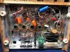
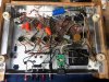
I apologize but I'm struggling with identifying a bypass cap? So for terminology sake, the 4 orange drops between the pre and power tubes are 'coupling caps' Struggling to identify a bypass cap(s) Any help from my pictures? :bye:
 
I apologize but I'm struggling with identifying a bypass cap? So for terminology sake, the 4 orange drops between the pre and power tubes are 'coupling caps' Struggling to identify a bypass cap(s) Any help from my pictures? :bye:
The bypass cap is one of the sections in the stock can. It's the one that's lower voltage. From your pic, it might have been replaced with that blue cap. Check to see if the value is similar to what's on the schematic.

In stock form, the amp has a single cathode resistor and a single bypass cap.

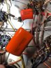
Looking at your pic again, please make sure that blue cap is secure. It looks to be just hanging there my its leads which are rather long so they can't be offering much support.
 
right, in the can. If its been replaced it would probably be outside the can. Should be tied into the big resistor on the bottom side. Trace that yellow wire. Should connect all the tubes together, go to the pot, and somewhere along the way it ought to tie into a capacitor.
 
Yellow connects all the tubes together and ties to the center tap of that pot. On that last tube the large (ceramic?) resistor does meet on the same pin. From the pot center tap a 25uf/50v cap goes to the negative (-) on the new can cap. Also on the negative (-) new can cap is a 10uf/500v that runs to a 6EU7. The can cap is a 50ufx50uf/500v. I know when I replaced that and found it to be a suitable replacement.

Hope I'm not driving everyone nuts because I'm enjoying it.

Also, I'll get that blue guy secured!
 

Attachments

  • IMG_2760.jpg
    IMG_2760.jpg
    141.2 KB · Views: 20
ok the black cap between the pot and the terminal on the can is your cathode bypass cap. Black wire goes from that terminal to chassis to complete the circuit. One end of the resistor goes to pin 3 along with the yellow wires so it does appear to be wired up properly. The cap is electrically across the resistor, but not physically. Not a bad thing, the heat from the resistor will not do the cap any favors.
 
Two things are confusing me. (big surprise there) Large black wire (looks like lamp cord 1/2) Is it connected to the ground tab? Or is it going out the hole that the ground tab makes in the chassis? And is the other end soldered to the can cap? The other thing: is the large blue polarized cap in series with a cap in the can? Shouldn't that cap be grounded to the chassis on the negative side of the cap?
 
What looks like lamp cord runs between the top mounted power switch and the fuse. The blue cap does ground to the negative side of the new can cap.
 
Back
Top Bottom