Correct, and you likely won't see it listed. But you can get an idea by looking at what the duties are in the circuit for a particular capacitor. Take the main power supply capacitors for example. What is the max current draw on the label on the unit? That will give you an idea. If it is 3A, then you want to stay above that for those caps. What is the current draw for the output amp itself in one channel? Say it is 1.3A at full volume. Then you want no less than that when choosing a replacement. Most caps on a tone control board will be in the lower mA range except for the power reserve caps. There you want to stay in the mid to upper mA range so the transistors aren't starving when the main amp is sucking power from the transformer. A coupling cap for signal is usually small in current draw so small 8x11mm caps are fine. Decoupling can vary depending on where. Speaker coupling caps should be quite a bit above the current the speakers will draw at extreme low frequencies. A basic rule of thumb (for me) is to avoid going a lot smaller in physical size compared to the original. All new caps will be somewhat smaller in size anyways.I don't think I've seen a current rating listed on the caps for this unit.


You are using an out of date browser. It may not display this or other websites correctly.
You should upgrade or use an alternative browser.
You should upgrade or use an alternative browser.
Both of those should be fine.The main issue I have is, with a given cap manufacturer, there are multiple results for the same capacity, type, and max voltage. Being my first recap, I still don't know which to choose.
I've seen many values substituted for the originals on the power supply board. The below seem to be the most common (the values in parentheses are the originals).
C803 - 470uf/63v (470uF/63V)
C804 - 220uf/50v (100uF/50V)
C805 - 470uf/50v (330uF/50V)
C806 - 220uf/50v (100uF/50V)
I'm curious if the ones listed here will be satisfactory, or if I use different ones.
https://www.mouser.com/ProductDetail/Nichicon/UPW1H221MPD6?qs=sGAEpiMZZMtZ1n0r9vR22UXbiauPutPBXgMydADrQaE=
and
https://www.mouser.com/ProductDetail/Nichicon/UPM1H681MHD6?qs=sGAEpiMZZMtZ1n0r9vR22bWlSlpQNIMtXjQpFhGVLdA=
Thanks!

Steven Tate
CEO Flat Forehead Soc.
Different caps of the same rating generally mean different package size and/or terminal distance. One may be tall and thin, and the other be short and fat, with all of the same values. Basically, if it will fit, it will work. But try to get a size a terminal distance that matches as close as possible to what you have - or smaller.
I always try to get lead spacing as close as possible. It definitely makes things easier. Getting caps of the same "value" also includes ripple current rating, dissipation factor, leakage, etc. That's why you'll see those columns on Mouser (and others). Take those two that David_NC linked to. Scroll on down and you'll see more parameters. Now follow this link below. At the top you can pick your desired parameters. Then scroll down a little, and across all the columns. You'll see different ripple current for different physical sizes that otherwise have the same capacitance/voltage ratings (among other factors). So your statement of "generally mean..." isn't quite true. Although it is true some of the time. https://www.mouser.com/Passive-Comp...ectrolytic-Capacitors-Radial-Leaded/_/N-75hqwDifferent caps of the same rating generally mean different package size and/or terminal distance. One may be tall and thin, and the other be short and fat, with all of the same values. Basically, if it will fit, it will work. But try to get a size a terminal distance that matches as close as possible to what you have - or smaller.
Just willy-nilly throwing in a capacitor that only meets capacitance, and voltage, might "work", but is it working properly? And will it keep working?
I have a question about some of these values. I listed the ones in my unit in bold, which match the values in the service manual. I notice that some of these are significantly different from what's specified. Is there a reason that they vary so much - better performance, unavailable original values, values changed in later units by factory, etc?
my apologies, I didn't footnote my work!

I got these values {not the p/n's} either from My try at a Really Nice Rebuild Marantz 1060 by member "bktheking" or from member "Leestereo"
another useful post is Marantz 1060 Recap but I haven't used any of that (yet).
here's where my favorite quote from Abraham Lincoln is useful: "don't believe everything you read on the internet". of course if you deviate from the original values you are responsible for the outcome. I accepted that responsibility when I made the listed deviations on my unit. I've gotten a couple of years out of it and seen/heard no reason to be concerned.
1060 C803
Service Manual values: 470µF, 63V
Mac used: 1000µF, 50v
"Leestereo" comment: Filtering, can increase, check lead spacing
1060 C804
Service Manual values: 100µF, 50V
Mac used: 220µF, 50v
"Leestereo" comment: Regulator multiplier
1060 C805
Service Manual values: 470µF, 63V
Mac used: 680µF, 50v
"Leestereo" comment: Filtering, can increase
1060 C806
Service Manual values: 100µF, 50V
Mac used: 270µF, 50v
"Leestereo" comment: Filtering, can increase
1060 C003
Service Manual values: 3000µF, 55V
Mac used: 10000µF, 80v
AMB_IV comment: The Nichicon I used for C003 is a monster. it has an OD that fit well in the original clamps. but it clears the underside of the case by 1mm or so. I was sweating for a while

1060 C006, C007
Service Manual values: 4700µF, 80V
Mac used: 6800µF, 63v
AMB_IV comment: C006, and C007 were selected because they had an OD that fit well in the original clamps.
I don't recall having any lead spacing issues but I can't promise you the p/n's I provided fit 100%. they didn't crash into any adjacent parts!

David_NC
Super Member
Update: Last night, I got C803, 804, 805, and 806 on the power supply board replaced. I'll power it up on a DBT later and see how it goes. If there's no smoke, sparks, or bright bulb on the tester, I'll give it a shot with my test speakers. If that goes well, I'll replace the two diodes and transistor and test again. After that, the main caps will be replaced. It looks like C003 is going to be close... it appears that the cover may just clear it, or not! It all went well despite that damned glue. I got off the chunky parts, but the areas where it spread thin are still there. The only issue I had was partially removing a resistor instead of a cap; it's hard to tell where the leads are sometimes. At least I left enough of the lead to solder it back.
As for that glue... what was the purpose of it? I can maybe see it being needed on much larger caps, but this unit doesn't have any that big, other than the ones held by a clamp. Do manufacturers still use glue like this? I don't remember seeing it much previously.
As for that glue... what was the purpose of it? I can maybe see it being needed on much larger caps, but this unit doesn't have any that big, other than the ones held by a clamp. Do manufacturers still use glue like this? I don't remember seeing it much previously.
Almost everyone used glue back then. Partly for assembly to glue caps in, then solder at the next station. And partly, especially larger caps, to prevent them from breaking loose in transport/shipping to prevent damage. Some assembly workers just blobbed it everywhere, where some were very "neat" with it. Different glues are used nowadays and is not needed as much because of smaller modern components.Update: Last night, I got C803, 804, 805, and 806 on the power supply board replaced. I'll power it up on a DBT later and see how it goes. If there's no smoke, sparks, or bright bulb on the tester, I'll give it a shot with my test speakers. If that goes well, I'll replace the two diodes and transistor and test again. After that, the main caps will be replaced. It looks like C003 is going to be close... it appears that the cover may just clear it, or not! It all went well despite that damned glue. I got off the chunky parts, but the areas where it spread thin are still there. The only issue I had was partially removing a resistor instead of a cap; it's hard to tell where the leads are sometimes. At least I left enough of the lead to solder it back.
As for that glue... what was the purpose of it? I can maybe see it being needed on much larger caps, but this unit doesn't have any that big, other than the ones held by a clamp. Do manufacturers still use glue like this? I don't remember seeing it much previously.
I recently jump from point to point rebuilds on tube amps and tried my hand on circuit boards. I wouldn't suggest starting out with a Marantz 4270 but that's what was in front of me.
I started by having in place a nice Hakko soldering station and nice vacuum desoldering station.
As with the tube amps I used tried and true components from a seller on the the bay. Peace and love puts some nice stuff together at a very reasonable cost. Takes all the guess work out for me.
The power supply was done first and then the tone board. There is more to be done but at least I feel comfortable leaving it on when I leave the room. And of course it sounds alot cleaner and tighten up the frequency response.
I do have a 1060 and the kit for power supply and tone board. (No affiliation to seller)
Should of started with the 1060. Easier to navigate not to mention about 35 pounds lighter.
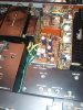
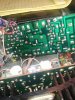
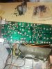
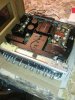
I started by having in place a nice Hakko soldering station and nice vacuum desoldering station.
As with the tube amps I used tried and true components from a seller on the the bay. Peace and love puts some nice stuff together at a very reasonable cost. Takes all the guess work out for me.
The power supply was done first and then the tone board. There is more to be done but at least I feel comfortable leaving it on when I leave the room. And of course it sounds alot cleaner and tighten up the frequency response.
I do have a 1060 and the kit for power supply and tone board. (No affiliation to seller)
Should of started with the 1060. Easier to navigate not to mention about 35 pounds lighter.
Last edited:
David_NC
Super Member
I recently jump from point to point rebuilds on tube amps and tried my hand on ciruit boards. I wouldn't suggest starting out with a Marantz 4270 but that's what was in front of me.
I started by having in place a nice Hakko soldering station and nice vacuum desoldering station.
As with the tube amps I used tried and true components from a seller on the the bay. Peace and love puts some nice stuff together at a very reasonable cost. Takes all the guess work for me.
The power supply was done first and then the tone board. There is more to be done but at least I feel comfortable leaving it on when I leave the room. And of course it sounds alot cleaner and tighten up the frequency response.
I do have a 1060 and the kit for power supply and tone board. (No affiliation to seller)
Should of started with the 1060. Easier to navigate not to mention about 35 pounds lighter.
View attachment 1718824 View attachment 1718826 View attachment 1718828 View attachment 1718829 View attachment 1718830
I started with tubes, too. Mine was an ST-70, which is a great beginner tube component. I can’t imagine a better documented and supported amp. Def stay away from Pioneer tube receivers. I’ve got two, and I get scared when I look at the undersides! I’d also recommend a 1060 as a beginner SS unit. It’s laid out logically, has relatively roomy boards, and uses easily available parts that are affordable. The ones I have are very well built, too. I have a Kenwood KA-9100 integrated amp. That one also looks really involved and would not be good as a first restoration candidate.
I can relate to what you say about the Japanese receivers. One of my first tube restores was a Sansui 1000A. I think I covered every cap in the unit. There are lots of them not to mention the necessary resistors. Thanks to Jim Mcshane for his supplies and support, and there are alot of others on this wonderful forum. They help me through alot of my rebuilds.I started with tubes, too. Mine was an ST-70, which is a great beginner tube component. I can’t imagine a better documented and supported amp. Def stay away from Pioneer tube receivers. I’ve got two, and I get scared when I look at the undersides! I’d also recommend a 1060 as a beginner SS unit. It’s laid out logically, has relatively roomy boards, and uses easily available parts that are affordable. The ones I have are very well built, too. I have a Kenwood KA-9100 integrated amp. That one also looks really involved and would not be good as a first restoration candidate.
All in all it is a very rewarding hobby once we get these gems back up to their old glory.
Good luck to you and your work on them.