• The move to the new server is done. There are some software and database maintenance updates in process. This has us passing the hat around to help out. We appreciate any donations. Seriously, even a dollar helps. The payment page may be found here - https://www.audiokarma.org/support.html

Marantz 1060 sound ruined after recap of tone control board?

sosico

New Member
Hi,

This is my first post after reading a lot here in Audio Karma, it's regarding the signal path in the Marantz 1060.

I have started my little recap project of this unit and I was very happy with the results sound wise when I did the P800 board, it sounded so much better.

After this I recapped the P400 tone control board. This is when my project went downhill.

The sound of the unit has changed for the worse, it sounds metallic and harsh. I thought at first that I had to wait for the break in, but I have been using the unit for months and I still don't like the sound after the recap. I wonder if I chose the wrong kind of capacitors for the signal path. I don't know exactly how to tell which capacitors are in the signal path.

I used panasonic FC on C403 C404 C409 C412 C413. The rest of the capacitors were Nichicon FG and KZ.

Any clues on what was wrong? and which of the capacitors in the P400 board are in the signal path?

Thanks a lot
Nelson
 
Register to hide this ad
Is it both channels that sound bad or just one?

Is there any lack of bass or treble?

Is there any distortion? Metallic and harsh does sound like distortion but this is subjective.

Did you check to make SURE you got the polarity correct when you replaced them?

Did you replace electrolytic caps with electrolytics and films with films?

Check to make sure you didn't short any controls out.

charles
 
Have you tried putting the original capacitors back in? You've checked your work, no solder bridges, cold joints, caps installed backwards?

Did you install the electrolytics one at a time, observing the polarity of the original capacitor installation, and not the circuit board or the schematic?

I think that the 1060's tone board will be similar, if not identical, to that of the 2230, and I think that there are two or four electrolytics installed strangely on that board -- they neither go to their designated markings on the board nor do they observe the polarity marking on the board.

I think that it's two per channel, a 1uf and a 3.3uF in each. Tom would know more than me since he's done more of them.

(edit: sorry for the repetition, Charles -- you posted while I was composing)
 
A recap sometimes results in a reduction of warm sound. When that happens, it is likely because the warm sound was not supposed to be there - a result of bad caps.
 
Yes I faced the same problem when I recapped the tone board of my 2265B . The highs sounded metallic and piercing. I used Panasonic FC and FE for the recap of the tone board.

Everything went well until the caps on the tone board were replaced. It was a complete disaster :tears:

Kinda disappointed because I took great care to ensure the polarity of the caps I replaced was correct. I also noticed the polarity printed on the board does not necessary match the schematic. The caps were replaced exactly as it came out.
 
Hi,

This is my first post after reading a lot here in Audio Karma, it's regarding the signal path in the Marantz 1060.

I have started my little recap project of this unit and I was very happy with the results sound wise when I did the P800 board, it sounded so much better.

After this I recapped the P400 tone control board. This is when my project went downhill.

The sound of the unit has changed for the worse, it sounds metallic and harsh. I thought at first that I had to wait for the break in, but I have been using the unit for months and I still don't like the sound after the recap. I wonder if I chose the wrong kind of capacitors for the signal path. I don't know exactly how to tell which capacitors are in the signal path.

I used panasonic FC on C403 C404 C409 C412 C413. The rest of the capacitors were Nichicon FG and KZ.

Any clues on what was wrong? and which of the capacitors in the P400 board are in the signal path?

Thanks a lot
Nelson
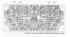
Did you install the caps EXACTLY like the originals? Did you get the polarity right? Note that they made the board wrong and C414 and C415 don't go where the silk screening indicates. They are shown correctly the attached diagram. This applies to the 2230, 2245 and 2270 models too, IIRC.

Tom
 

Attachments

  • 1060 pre-tone.jpg
    1060 pre-tone.jpg
    87.5 KB · Views: 479
Thanks all for the responses:

Airtime:
Is it both channels that sound bad or just one?

Both channels the treble sounds metallic.

Is there any lack of bass or treble?

No problems with that. There is bass and (metallic kind of) treble.

Is there any distortion? Metallic and harsh does sound like distortion but this is subjective.

I don't think that I would call it distorsion. Is that the treble sounds unnatural. metalic harsh.

Did you check to make SURE you got the polarity correct when you replaced them?

To the best of my knowledge I checked that every polarity is fine. In cases where the silk screening indicated something that was not correct I took pictures of the old capacitors to make sure that I installed the new ones exactly like the old ones.

Did you replace electrolytic caps with electrolytics and films with films?
I have replace the following caps, all electrolytics
C403 1uF 50V ES Panasonic FC
C404 1uF 50V ES Panasonic FC
C405 10uF 35V KZ
C406 10uF 35V KZ
C407 3.3uF 50V FG
C408 3.3uF 50V FG
C409 100uF 35V ES Panasonic FC
C410 3.3uF 50V FG
C411 3.3uF 50V FG
C412 .47uF 50V ES
C413 .47uF 50V ES
C414 1uF 50V Bipolar EP
C415 1uF 50V Bipolar EP

I also replaced The C401-402 0.22uf 50V Mylar's with 0.22uf 50 Polyproplene's.
0.22uf 50V Mouser # 539-168224J50C-F

Check to make sure you didn't short any controls out.

How do I check there are no shorts? Could you point me to some newbie links?


stahlhart: I cannot put the original capacitors back in , I threw them away. I was confident the sound was going to improve due to my success with the Power Supply Board.


PetrolHD: What did you do with your tone control board? Did you recapped it again?

catrafter: To the best of my knowledge I installed them like the originals. I took pictures of the c414 and c415 when I was recapping because I remember they didn't match the silk screening. These are bipolars cap.


Does anybody knows which of all the capacitors in the tone board are in the signal path? (all of them/none of them / Which ones?) and assuming I did not make any mistake replacing them, I would like to know if using the panasonic FC on the tone control board was a bad move.

Thanks again for all your help
 
I suggest taking a picture of the P400 (front and back) and post it here for the cat man to take a look at...
 
C407, C408, C410, C411, C414, C415, C416, & C417 are all signal path caps. I'd highly recommend Elna Silmic II caps, except for C416 & C417, where I'd use a 50V Panasonic stacked film cap.

C407, C408, C410, C411, C414 & C415: 4.7µf 25V Elna Silmic II, Digikey #604-1049-ND
C416 & C417: 0.47µf 50V Panasonic stacked film, Digikey #P4671-ND

Edit: It looks like the pads for C416 and C417 are designed for an axial cap. In that case, I'd look at a metallized polyester or polypropylene cap to go there instead (the lead spacing on the stacked film is only 5mm). If you give the pad spacing for these caps, I'll look in the catalog and see what might be appropriate. Might be able to change C414 and C415 to a 1µf film cap also if the leads spacing is ample enough. Check both.
 
Last edited:
C407, C408, C410, C411, C414, C415, C416, & C417 are all signal path caps. I'd highly recommend Elna Silmic II caps, except for C416 & C417, where I'd use a 50V Panasonic stacked film cap.

C407, C408, C410, C411, C414 & C415: 4.7µf 25V Elna Silmic II, Digikey #604-1049-ND
C416 & C417: 0.47µf 50V Panasonic stacked film, Digikey #P4671-ND

Edit: It looks like the pads for C416 and C417 are designed for an axial cap. In that case, I'd look at a metallized polyester or polypropylene cap to go there instead (the lead spacing on the stacked film is only 5mm). If you give the pad spacing for these caps, I'll look in the catalog and see what might be appropriate. Might be able to change C414 and C415 to a 1µf film cap also if the leads spacing is ample enough. Check both.

Would it be worthwhile to take a similar approach for C751 and C753 on P750?
 
Thanks all for the responses:


PetrolHD: What did you do with your tone control board? Did you recapped it again?

Thanks again for all your help

Not yet , but I intend to replace the signal path caps on the tone board with audio caps. But I have to learn to differentiate what is signal path and non signal path first.
 
Would it be worthwhile to take a similar approach for C751 and C753 on P750?
Any time you can possibly change an electrolytic to a film cap, I consider this a good thing. Even the cheapest low-tech film cap can carry many times the current of the same capacitance value in an electrolytic (as an example, albeit not necessarily relevant in the present application), and will, in 9999 times out of 10,000, result in less coloration of the original signal.

If intentional coloration is your goal, then lots of electrolytics (or one vacuum tube) should be your version of nirvana.
 
You could start replacing the signal path caps back with origonals, a few at a time, to see which caps are the most significant.
 
Echowars and all:

Thank you very much for the responses. I will follow EW advice and replace the caps on the signal path on the P400 boards with the ones he suggested and let you know of the results.

Thanks again!
 
C407, C408, C410, C411, C414, C415, C416, & C417 are all signal path caps. I'd highly recommend Elna Silmic II caps, except for C416 & C417, where I'd use a 50V Panasonic stacked film cap.

C407, C408, C410, C411, C414 & C415: 4.7µf 25V Elna Silmic II, Digikey #604-1049-ND

EW: Looking at the values of these caps
C407,C408,C410,C411 are 3.3uf 50V originally, Would I have problems using the 4.7uf 25v you recommended?

C414,C415 are bipolar 1uf 50v...same question. Do I buy bipolars here or just use the Elna Silmic II, Digikey #604-1049-ND for all of them?
 
Regarding last post I just realized that the original voltage is 25v not 50v. I bought 50v for the recap.

I still have the question about the difference in the microfarads.
 
My guess is it's for a slight boost in (or less attenuation of) lower frequency response. At least that was why I went with the recommendation to up the output capacitors to 4700uF from 2200uF in my 2230.
 
The larger value will not hurt a thing, and might help the bottom end response (and area where this amp can use some help anyway).
 
Back
Top Bottom