• The move to the new server is done. There are some software and database maintenance updates in process. This has us passing the hat around to help out. We appreciate any donations. Seriously, even a dollar helps. The payment page may be found here - https://www.audiokarma.org/support.html

Marantz 1122DC Restoration

Hello Mates!

Newbie here and know this is an older thread, but I'm hoping someone can answer my question.

There is 1122dc for sale but seller notes that turn-on delay is 8-12 seconds. That sounds long, but what is normal?

Cheers,

dadsnave
 
Thank you Steven Tate for your response.

I'm hoping for a response directly from someone with firsthand experience that has a known-good -- or freshly refurbished -- 1122dc like MBuras that started this thread.

Cheers,

dadsnave
 
This piece left my collection a while ago so I can’t comment on it specifically but @Steven Tate is right about the timing. Usually 3-5 seconds on a healthy receiver/amplifier.

I saw that listing and my first thought was it needs restoration. There are likely one or more components failing in the relay circuit. And given it’s over 40 years old a full restoration is probably in order anyway. “Serviced” and a deoxit bath does not count as restoration in my book.

Good luck with your search.

Mike
 
Thank you @MBurris for your reply. Think I'll pass on the "8-12 seconds" unit.

I'm an old electronics tech by education, but a computer programmer by day job. I'd tackle a restoration myself, but day job is all-consuming.

Anyone know a good source to recommend for buying already-refurbished vintage Marantz? Or where to send one to for refurbishing?

(I'm in SE Michigan.)
 
PE01 Tone Control Board = Done!

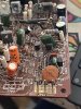
Here's what I started with:
View attachment 800201

As shown above all 4 of the push button switches and the selector slide were pulled from the board, pulled apart and cleaned. All capacitors (electrolytic, film, ceramic) and all transistors were replaced with modern equivalents.

Here is the end result:
View attachment 800202

And here are the details. None of the original parts were failing or damaged. Replacement was a personal choice. The only real change in spec was the local DC filter and that was increased to provide the best possible ESR/ripple rating in that position. I also thought the cataloging of the board could help future techs looking for details on this unit.

CE01/02 - 50v/1uf low leakage electrolytics [manual error says 0.47uf] were replaced with Panasonic ECW series polypropylene films. Plenty of space for these nice films on the upper right.
CE05/06 - 50v/4.7uf low leakage electrolytics were replaced with WIMA MKS2 polyester films.
CE07/08 - 50v/200pf ceramics were replaced with Kemet 5% C0G ceramics. 220pf was the closest available value. Important to try and stick with 5mm leads here. Makes installation so much easier.
CE09/10 - 50v/1500pf films were replaced with Nichicon QYX series polyester films of the same value.
CE11/12 - 50v/5600pf films were replaced with Nichicon QYX series polyester films of the same value.
CE13/14/15/16 - 50v/0.018uf films [manual error says 0.033uf] were replaced with Kemet MMK series polyester films of the same value.
CE17/18 - 50v/6800pf films were replaced with Nichicon QYX series polyester films of the same value.
CE19/20 - 50v/0.047uf films [manual error says 0.47uf] were replaced with Nichicon QYX series polyester films of the same value.
CE21/22 - 50v/3.3uf low leakage electrolytics were originally slated for Panasonic ECW series polypropylene replacements. Plenty of space to the left of the sliders but I apparently forgot to order them so used WIMA MKS2 polyester films I had on hand. Still a quality replacement.
CE25/26 - 50v/1000pf films were replaced with Nichicon QYX series polyester films of the same value.
CE27/28 - 50v/0.1uf films were replaced with WIMA MKS2 series polyester films of the same value.
CE29/30 - 50v/0.015uf films [manual error says 0.027uf] were replaced with WIMA MKS2 series polyester films of the same value.
CE31/32 - 50v/0.082uf films were replaced with Panasonic ECQ series polyester films of the same value. These were chosen because the lead spacing is larger in this position. The leads still need to be bent but there plenty of extra on the Panasonics.
CE33 - 50v/100uf electrolytic [local DC filter] was replaced with a Nichicon UPW series [low esr, high ripple current] electrolytic rated at 63v/180uf.
CE83/84 - 10v/100uf electrolytics were replaced with Nichicon UPW series [low esr, high ripple current] electrolytics rated at 16v/100uf.
CE85/86 - 50v/40pf ceramics were replaced with Kemet 5% C0G ceramics. 39pf was the closest available value. Important to try and stick with the 5mm leads here. Makes installation much easier.
CE87 - 50v/22uf electrolytic [board polarity markings reversed!] replaced with Nichicon UKL low leakage series of the same value.
CE88 - 50v/0.47uf electrolytic was replaced with WIMA MKS2 series polyester film of the same value.

QE01/02/05/06 - 2SC1222 to-92 transistors were replaced with Fairchild KSC1845FTA's. Same pinout. Gain matched.
QE03/04/07/08 - 2SA750 to-92 transistors were replaced with Fairchild KSA992FBU's. Same pinout. Gain matched.

Hi. nice job. I'm also doing the recap on my 1122dc right now. I noticed two capacitors (ce81 and ce82) were missing. now I see the same situation on Your amp. Do You now somethings about that?
I also noticed the capacity differences in the documentation compared to the built-in capacitors.
I have not yet replaced the AC / DC capacitor, I see that you use 1uf, while the documentation says 10uf. I replaced all the Elco capacitors in the amp and tone module with Nicicon ukz. Same as You, I replaced the couplink capacitors in the tone section with WIMA MKS2.
I didn't replace the other active and passive components becouse everything works with no problems.
The amp sounds fantastic now :)
 
Been a long time since that one. Don’t really recall much about it other than the service manual was riddled with errors. More than usual for Marantz. Just stick with the values that were factory installed and you should be fine.
Cheers!
 
C701/702 - 50v/100pf C0G ceramics [manual error notes them as film said:
. Even though these were already C0G ceramics I replaced them with the same because modern replacements are about 1/10 the size. Less chance of the big floppy disc getting pushed around in the future.

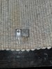
Hi, C701/702 are marked 100J. Doesn’t this mean they are 10pF, not 100pF?
 

Attachments

  • 32ED65AE-12D0-455F-803F-F67F72C48F95.jpeg
    32ED65AE-12D0-455F-803F-F67F72C48F95.jpeg
    159.3 KB · Views: 24
Wonderful rebuild MBuras.

Working on one right now and discovered something that may be very important for those replacing the driver transistors on the P700 board.
When rebuilding the board I had little resistance in between +46v and -46v. Very low ohms from 0,4 to 8,4 ohms.

Seriously couldn't find the issue until I noticed something very strange.
The new driver transistors, SA1381 and SC3503 both TO-126 package, are a bit different than the old ones.
The old types are completely insulated while the metal on the back of the new ones is connected to the collector.

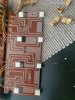
20220515_010304.jpg

Even when using non-conducting thermal paste, both collectors are connected through the heatsink.
This causes to short the +46v and -46v.
I used some Mica pads to insulate the TO3 transistors from the heatsink.
The red line is +46V
The blue line -46v

The transistors Q725 with Q721 and Q727 with Q723 within the blue circles are connected on the heatsink.
Take a look at the pictures.
Be advised and make sure you measure between the red and white wires.
You should measure somewhere around 17,25K in normal polarity and around 5K in reverse.

1122dc.png
 
Last edited:
I would like to add a few things to this thread making it easier to find parts for this amp and maybe a few others.
My 1122dc has connectors for the output transistors. You just shove the complete heatsink into the pcb connectors.
As you can see on the picture below, some of the PCB-connectors were heavily burned due to a defect.

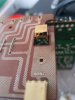
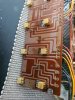
20220502_171447.jpg 20220502_171459.jpg

I was able to replace them with the exact type Molex connector:
The can be ordered at Digikey for only €0,49.

https://www.digikey.nl/nl/products/.../26499?s=N4IgTCBcDaIO4FsDMAGFBGAtAOwCYgF0BfIA

Now, the same board, cleaned and the connectors replaced.

20220502_172540.jpg
 
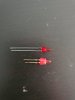
I also found a replacement for the power LED in the faceplate. It has the same voltage and the tip may be a tiny bit smaller but it fits like a glove.

For Digikey:

https://www.digikey.nl/nl/products/detail/sunled/XLUR13D/4901653 (10mA)
https://www.digikey.nl/nl/products/detail/sunled/XLMDK13D/13559322 (20mA)

For Reichelt:

https://www.reichelt.nl/nl/nl/flat-...led-2mm-ft-rt-p31619.html?&trstct=pos_0&nbc=1

They fit perfectly into the connector, you only need the anode/cathode to be cut by an inch or so. See what suits for your amplifier.
Used them on the 1122dc and the 170dc, so most likely will fit others too.

20220515_164247.jpg
 
Does anyone have a slide pot to donate? Or where can I buy one?

I rebuilt my 1122DC PE00 board and now I have no sound, using only the AMP I notice that P700 works as a charm, so definetively is the PE00. I only suspect about the pot that I cleaned up.

Ill start to go one by one of the old caps/transistors if culpright is one od those.
 
Hi everyone, I have a Marantz 1122DC and I’d love to follow the recap process being discussed, but I’ve noticed some errors and changes in the original schematic, and I’m a bit afraid of doing something wrong. Does anyone know if there’s a site in Europe that sells a complete replacement kit? Or maybe someone here offers it? I’m based in Spain and I can only find it on eBay in the US, but with the current tariffs it’s just not feasible. I’d really appreciate any help or recommendations. Thanks so much!
 
Best you follow what’s in your amp and order the bits you need rather than rely on the kit which can have potential different parts
 
Back
Top Bottom