• The move to the new server is done. There are some software and database maintenance updates in process. This has us passing the hat around to help out. We appreciate any donations. Seriously, even a dollar helps. The payment page may be found here - https://www.audiokarma.org/support.html

Marantz 140 power amp rebuild

mazinkaiser

Active Member
Hi guys first of all a special thanks to Patfont and Flaxmill19 for all their outstanding posts, documentation and support for the community you guys are truly assets to audiokarma keep up the great work!!

So i finally found some time to start my rebuild on the wonderful Marantz 140 power amp

I got the amp in decent shape from its original owner with distortion issues on both channels i have cleaned both gain pots with the usual deoxit treatment and orderd caps for it. The owner had some work done to it before looks like the only thing that was done to it was the filter cap was replaced everything else is original so a recap is in order!
 
Last edited:
Register to hide this ad
IMG-20190424-WA0003.jpeg

Once a couple of screws get removed it opens up like a box. Its important to note that unlike other marantz ive worked in the past this one doesn't have a bottom cover you can remove the actual bottom cover is where the main transformer rest which is super heavy so everything is unassembled from there
 
Last edited:
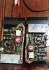
This amp is completely modular and is an absolute pleasure to work you just remove s couple of screw and uplug the pin connectors that go to each channel board and they come out nice and easy for you to work on

20190426_225107.png
 
With both channel boards removed i started cleaning the dust from the inside like i said before just great engineering by marantz

IMG-20190424-WA0015.jpeg
 
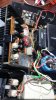
On a previous post Flaxmill19 had mentioned how dirty the connectors for the channel boards get and he replaced them with some gold plated connectors as i have no access to the tool he was using i decided to do the next best thing i desoldered the pin connectors and used a combination of alcohol and a plastic eraser to remove all the corrosion

BEFORE:
IMG-20190424-WA0046.jpeg


AFTER:
IMG-20190424-WA0048.jpeg
 

Attachments

  • IMG-20190424-WA0048.jpeg
    IMG-20190424-WA0048.jpeg
    42.3 KB · Views: 3
I have finished recapping all the boards will post more pictures tomorrow i have adjusted all settings per service manual but im still getting distortion on both channels if playing loud or on high segments of the song as they distort together or independently the peak lights turn on and off at the moment it happens any ideas? Thanks
 
Very nice work! Hopefully, someone can give you some guidance in chasing down the distortion. It might take tracing down with a scope to see where the signal starts distorting.
 
Are you sure you are not over driving the amp and causing it to clip?
A pair of dummy loads and an O'scope will tell you what's going on.
Perhaps the power supply 'rail' voltages are low causing it to clip prematurely.
Look for plus and minus 55V going to each amp module.

Tom
 
Thanks for the comments and help guys unfortunately i dont have access to an oscope i had bought a refurbished old tektronix and it got damaged during shipment
 
Are you sure you are not over driving the amp and causing it to clip?
A pair of dummy loads and an O'scope will tell you what's going on.
Perhaps the power supply 'rail' voltages are low causing it to clip prematurely.
Look for plus and minus 55V going to each amp module.

Tom


I dont think im over driving it speaker volume is very low on 90db efficiency speakers that are easily driven to painful volumes by my sansui au101 15 watt amp vu meters do not seem to indicate this either. So i dont have access to a instruction manual for this but when the needle on the vu reaches +3 is when amp delivers 75 watts or is it at 3?
Where do i check for those voltages or whats the process thank you
 
The meter adjustment is kind of odd on this one, 0vu is set to indicate about 10W (using RMS voltage). Full scale is 32W (using RMS voltage)
DO NOT USE A DIMBULB for the following test.

1. Turn both gain controls all the way down.
2. Unplug the unit.
3. Set your meter to read DC volts. Connect the black meter lead to the chassis. Connect the red meter lead to the filter capacitor post with several red wires attached to it.
4. Plug the unit in, wait 30 seconds or so, then note the voltage reading for approx +55VDC.
5. Unplug the unit.

6. Set your meter to read DC volts. Connect the black meter lead to the chassis. Connect the red meter lead to the other filter capacitor post with several white wires attached to it.
7. Plug the unit in, wait 30 seconds or so, then note the voltage reading for approx -55VDC.
8. Unplug the unit.

With speakers connected and music playing, advance the gain controls until the problem just starts, then repeat the above procedure starting at step 2.
Note the two voltage readings.

Report back.
I'm concentrating on the rail voltage because that is where the 'work' seems to have been performed.
Make sure that the orange wire is plugged on to J711 and the brown is plugged onto J712 for each power amp module.

Tom
 
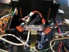
Wait a minute, looking at your pictures it is hard to tell, but are both posts of each large, blue filter capacitor connected?
The Positive post of the filter that has the White wires on the Negative post should connect to the 'bar' with the many black wires attached to it.
The Negative post of the filter that has the RED wires on the Positive post should connect to the 'bar' with the many black wires attached to it.

A really good photo of the tops of the filter capacitors would help.
DR140 fil (2).JPG


Tom
 

Attachments

  • DB140 new fil (1).JPG
    DB140 new fil (1).JPG
    80.4 KB · Views: 46
I dont think im over driving it speaker volume is very low on 90db efficiency speakers that are easily driven to painful volumes by my sansui au101 15 watt amp vu meters do not seem to indicate this either. So i dont have access to a instruction manual for this but when the needle on the vu reaches +3 is when amp delivers 75 watts or is it at 3?
Where do i check for those voltages or whats the process thank you

Ok with gain controls at lowest i read
On red wires 47.60
On white wires -47.63

After gain controls are set to where the problem starts

On red wires 47.77
On white wires -47.77

Is that low or should it be at 55 like you mentioned thanks again for all the help really learning alot
 
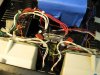
Heres a better picture of the filter caps
Is that correct? I havent changed anything from the previous picture this is how it came to me

IMG-20190427-WA0001.jpeg
 
also wanted to mention that the replacement caps used are rated 18000uf 50v as opposed to what the service manual reports at 13000uf 55v i believe is this correct and could it cause and issue with the amp operation with this increase?
 
Not sure if it’s just the pic, but I don’t see a big, hefty connection from the bar to the chassis. Notice the big strap making that connection in Tom’s photo. Also, I don’t know if it’s a real problem, but my understanding is that all of those black ground wires should be connected close together near the center of the strap. Again, see Tom’s pic. I’m interested to hear if Tom thinks either of these could contribute to the problem. Also, it’s probably correct, but verify that the bar goes from the negative post on the cap with red wires to the positive post of the cap with white wires.
 
Last edited:
Yeah i see what you mean Steven yeah curious to hear what tom thinks about this as well there is a single white wire the one thats in the middle of the bar that seems like it goes to the transformer then there is a set of two ground connectors and each one goes to the left and right heatsink for grounding then the rest if the ground cables i believe go to the amp board etc
 
Theres also what appears to be some binding post box on the right side of the filter caps where theres several wires and some resistors between two additional grounding spots that are held by two screws not sure if this is all stock?
 

Attachments

  • IMG-20190427-WA0005.jpeg
    IMG-20190427-WA0005.jpeg
    63.2 KB · Views: 49
That looks like your bridge rectifier that converts the transformer AC to DC before the filter caps. I do think you have a big grounding problem with those big caps.
 
Back
Top Bottom