• The move to the new server is done. There are some software and database maintenance updates in process. This has us passing the hat around to help out. We appreciate any donations. Seriously, even a dollar helps. The payment page may be found here - https://www.audiokarma.org/support.html

Marantz 2230 rebuild

goldswimmerb

Failed out of engineering, but look at me now!
Subscriber
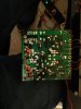
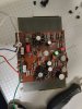
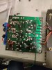
Hey guys, so I got a Marantz 2230 from a guy to do a rebuild of the audio path.

So far when testing I've noticed that one channel has much more bass than the other. It's made worse by the bass potentiometer which leads me to believe that it's a preamp issue.

Could it be the 2SC1000s in the preamp? Or a bad Bass potentiometer?

It was allegedly worked on in the past but I don't see anything that looks blatantly not stock.

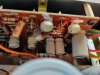
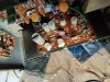
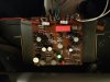
Pics attached though.
w8MuV1n.jpg
zWLcN42.jpg
z0jXHsJ.jpg
C4IK1dZ.jpg
 
Register to hide this ad
Since the 2230 has pre-main jumpers, it is easy to tell a preamp problem from a power amp problem.
If it is a power amp problem, bad electrolytic caps C753,754 on the power amps can cause this issue.
Check the service bulletin (M-2230-1) to be sure of polarity.

Tom
 

Attachments

Since the 2230 has pre-main jumpers, it is easy to tell a preamp problem from a power amp problem.
If it is a power amp problem, bad electrolytic caps C753,754 on the power amps can cause this issue.
Check the service bulletin (M-2230-1) to be sure of polarity.

Tom
Thanks for that, from these pictures are mine oriented right or wrong? Wording is a bit confusing in the bulletin imo.IMG_20191102_151450.jpg IMG_20191102_151318.jpg
 
Rebuilt the preamp board on a whim since I plan to do it anyway. Amplifier now seem perfectly balanced! Not sure if a bad cap or transistor but it works. Went with KSA992 for the 2SA493s and KSC1815 for the 2SC1000s, WIMA films for all small caps and Nichicon UPW for filters.

Upped the 10UF filters to 47uf, left the 100uf as 100uf since I seem to be out of 220 or 330uf ones that'll fit.

XyQix2h.jpg
 
Since the 2230 has pre-main jumpers, it is easy to tell a preamp problem from a power amp problem.
If it is a power amp problem, bad electrolytic caps C753,754 on the power amps can cause this issue.
Check the service bulletin (M-2230-1) to be sure of polarity.

Tom

Any idea what's up with the 220UF axial cap on the phono board? never seen that before.
 
There is a forward biased diode in series with the 35VDC power source to J706 on the Phono board. The axial capacitor connects from J706 to chassis ground.
It provides a bit more power supply isolation and filtering to the phono board.

The other Marantz receivers from this era don't have this. Sometimes the capacitor is as much as 470µF.

Tom
 
There is a forward biased diode in series with the 35VDC power source to J706 on the Phono board. The axial capacitor connects from J706 to chassis ground.
It provides a bit more power supply isolation and filtering to the phono board.

The other Marantz receivers from this era don't have this. Sometimes the capacitor is as much as 470µF.

Tom

Thanks for that! Is it worth increasing when I get to that board? Interesting that that cap and diode are completely absent from the schematic I have. Is the diode one that should be replaced as well, I'd assume not but just want to be thorough.
 
C011 and H009 are on the schematic inside the 2230 service manual. They’re just not on the board image because they’re not on the board but the rail right next to it. Just above the J706 pin on the large schematic (page 20, figure 20).
 
The diode is pretty robust, I don't usually need to replace it. 138AML axial caps from Vishay/Sprauge are nice, 105°C. I usually use a 470µF at 40V.

Tom
 
So, now that I've got the 4300 wrapped up I'm coming back to this thread. Going to be making any recommended modifications to this one, so if anyone has any suggestions hit me up.

So far I've made the upgrades to the tone board and preamp bard as per leestereos guide for the 2270.
My plans for now are:
1. Get all VD1212s out of here
2. Get all known to failure-prone transistor out of there (if anyone has a good list, aside from the top ten one here on AK which I use let me know)
3.Bump up the main filter and coupling caps in capacitance/voltage if possible
4. Add flyback diodes for protection of output devices.

I'll be updating this thread as I get to things, most of these are just done when I get bored at my day job.

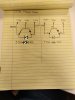
Heres my proposed schematic/crude drawing: (updated to be right since my original post was incorrect)
IMG_20191118_131652 (1).jpg
I failed circuit analysis so I had a fellow member OK it before posting, but more eyes is always better...
 
Last edited:
Alright, so I've gotten one amp board done, took forever since I was actively researching while I did it.

Things done:
All Electrolytic Capacitors replaced, mostly UKZ but one UES.
Input film Capacitor replaced with a WIMA film
Replaced expoxy diode/varsistor with a 1N4148
Added Flyback diodes.

IMG_20191119_233730.jpg
I did notice a few things while working on this one, so hopefully someone can answer my questions.

C753 is a 1UF 50V in my service manual, but was actually a 10UF 35v on my board. From the looks it's in the signal path so I swapped it to a UES bipolar. Did I make the right call here?

I saw threads about swapping out C761 for a WIMA for C0G ceramic, however my board does not appear to have a C761 at all. Is this just one of those wonderful undocumented changes from Marantz?

Would there be anything to be gained by swapping the C759 and C758 caps over to C0G types? I don't think they're in the signal path so I'd guess not?

Is there any benefit to changing Amy if the transistors on this board (namely H753/H754)? None seem failure prone but figured I would ask.

Also here's the back of the board:
IMG_20191119_233747.jpg
Anyone have any idea what that 100pf ceramic is for? Don't think it's in the signal path so I probably won't bother with it but figured I would ask.

Anything else worth changing that I missed?
Thanks!
 
C753 is a 1UF 50V in my service manual, but was actually a 10UF 35v on my board.

The 2230 errors, including this one, are pretty well documented in the sticky at the top of this forum. Once you click into that thread you can use the search box to search within it for specific models or any other keywords. :thumbsup:
 
The 2230 errors, including this one, are pretty well documented in the sticky at the top of this forum. Once you click into that thread you can use the search box to search within it for specific models or any other keywords. :thumbsup:

Figured that was the case. I guess SM errors were much more common back in the day.

Im still a bit confused as to why my C761 is nonexistant.
 
...saw threads about swapping out C761 for a WIMA for C0G ceramic, however my board does not appear to have a C761 at all...Also here's the back of the board:
View attachment 1677298
Anyone have any idea what that 100pf ceramic is for? Don't think it's in the signal path so I probably won't bother with it but figured I would ask...

The 100pF ceramic capacitor is C761: its part of the input low-pass filter (one lead is connected to the H751 input and the other is grounded) and hence is in the signal path.
 
The 100pF ceramic capacitor is C761: its part of the input low-pass filter (one lead is connected to the H751 input and the other is grounded) and hence is in the signal path.
Thanks! I didnt have a schematic/board Image that labelled that one.
 
Went back and finished up the amp board and did the PS board. Will have a separate post for.

I went back and replaced the 3 50pf ceramics with C0G types, don't think it'll make a difference but I like being thorough.
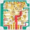
C761 which is on the back of the board in my units revision, was upgraded to a WIMA FKP. I did find this nice updated board image for the unit I have here:2230 P750 board layout color.jpg

Heres the front of my board now:
IMG_20191121_215323.jpg
Back:
IMG_20191121_214721.jpg

Also, I went to set the DC level and bias, I noticed that the bias was consistently jumping around by .3-.4mv, for example, with DC level set to 30V+-.1 I would set bias to 9.7mv with the pot and it would jump up and down between 9.6mv and 10.1mv. Should I worry about this? What would be causing this, a drifted driver perhaps?
 
0.4mV is very small. I wouldn't worry about it, you can probably get a bigger change by blowing on the 'bias' circuit.

Tom
 
0.4mV is very small. I wouldn't worry about it, you can probably get a bigger change by blowing on the 'bias' circuit.

Tom

The reason it concerned me was the speed it was changing, multiple times in a few seconds (pretty much continuously, never stabilizing), most other units I've dealt with will stabilize and then slowly move up and down.
 
Back
Top Bottom