• The move to the new server is done. There are some software and database maintenance updates in process. This has us passing the hat around to help out. We appreciate any donations. Seriously, even a dollar helps. The payment page may be found here - https://www.audiokarma.org/support.html

Marantz 2230 rebuild

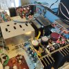
Alright so I finished up the PS board. The board appears to be similar to the one in the 2270, minus the relay circuit, so I applied similar upgrades.

Pic:
IMG_20191122_002247.jpg

H804/H805 were replaced with UF4004 diodes.
C803, which appears to be the main filter for the PS was originally 470UF/63V and was upgraded to a 1000UF/63V Nichicon UPW.
C804 and C806 appear to be the filters for the 14V and 35v regulated supply, originally 330UF/50v were upped to 470UF 50V UPW caps.
C805 which shunts the 14V Zener was originally 470uf/16v and was replaced with a 470uf 25V UPW.
C807 on the base of H803, was originally 3.3uf/35v, it was replaced with a 10UF 50v UFG.
H803 was originally a 2sc1213, I replaced it with a KSC2383 as I don't trust transistors in the "house" shaped packaging.

Lastly, I replaced the chassis mount 150 ohm/5w resistor with a 150 ohm/7W vitreous enameled type, the schematic has this one listed as 1kohm I belive but mine was most certainly a 150 ohm.
IMG_20191122_002221.jpg
I'll have to give it another listen at some point as I finished this up at 1AM last night and my hearing was shot from working in complete silence (the unit sounded rather harsh for some reason). If anyone has any objections to these upgrades let me know.
 
Last edited:
It's looking good!
Did you apply thermal compound to the bottom of the rectifier (where it touches the chassis)?

Tom
 
It's looking good!
Did you apply thermal compound to the bottom of the rectifier (where it touches the chassis)?

Tom

I have not, guess I need to? Is this the original rectifier for this model? Much different than those I have seen in the past. The power cable on this one isn't original so I was trying to figure out what else may have been touched.
 
The rectifier looks stock. I don't know if it is absolutely 'necessary', but I always apply thermal compound wherever I think it will help.

Tom
 
The rectifier looks stock. I don't know if it is absolutely 'necessary', but I always apply thermal compound wherever I think it will help.

Tom

I went back for a listening test today and it sounded pretty good. Went ahead and upped the filters and coupling caps in capacitance and oooooh boy does this thing sing. The previous low frequency cutoff made it a poor match for a few of my test tracks (some obscure electronic music that has moments where it drops down below 15hz if I recall). Before increasing those filters I would get a pretty hard clipping pop at 35 watts or so, now I don't even have to crank it to that point as it seems more low frequency sounds are making it to the output.
 
Just to close this off, I finished up the Phono Preamp and Main Filters.

Amp Picture:
IMG_20191124_220542_184.jpg

The two 2,200uF output coupling caps were upgraded to 4700UF Nichicon LGU capacitors,
647-LGU2A472MELC
The 4,700 UF main filter was replaced with a United Chemi-Con EKM 10k UF capacitor,
661-EKMH800VRT103MB5

I would have liked to use nicer looking caps here however this was what was available. It sounds great after the upgrade.

The Phono board:
IMG_20191125_213742.jpg
This was rebuilt as per the general recommendations. The only change from the norm is that I replaced the 2SC458s here with KSC1815s as I've found KSC1845s can cause unwanted oscillations (I think its related to gain as the hFe on the 458s is in the 200ish range and the 1845s that are readily available are in the 400 range) when the first 4 transistors are replaced. The 2SC1000s here were replaced with KSC1845s.
 
Thanks for using the correct diameter of capacitors so they fit the clamps!

Tom

Thats a rule for me, I hate having to wrap caps in tape to make them fit, so much cleaner when theyre the right size. I wish I could've found Nichicon Gold Tunes but they weren't available in the right size...

The only thing Im not 100% happy with is my work on the wire connections when removing the amp boards and filters I can never seem to get them to look clean when I put them back since the wire coating always seems to melt.
 
The plastic insulation melts really easy.

I cut the lugs off the old coupling capacitors first. Then I cut the plastic insulated wires off the lugs,then I un-solder the resistors and coils.
Strip and tin the wires carefully before attaching them to the new lugs, connect the resistors and coils ends, solder.

BH2230 filcc (4).JPG
 
The plastic insulation melts really easy.

I cut the lugs off the old coupling capacitors first. Then I cut the plastic insulated wires off the lugs,then I un-solder the resistors and coils.
Strip and tin the wires carefully before attaching them to the new lugs, connect the resistors and coils ends, solder.

View attachment 1686296
I drilled out the old lugs from the filter cap and coupling caps to not disturb the wiring. Then folded over the lug's holes, crimped them to the new snap-in lugs, and soldered. Made for a clean and easy swap.
 
Back
Top Bottom