

You are using an out of date browser. It may not display this or other websites correctly.
You should upgrade or use an alternative browser.
You should upgrade or use an alternative browser.
Register to hide this ad

My substitution list states 2N3440 as the replacement but I bought 2 and they both burned up. In an AK thread I saw that the KSC2383 is a substitution. Does anyone know? I have those in stock.
Are you using a dim bulb tester? If it's burning up you've got problems a new sacrificial transistor won't fix.
I now have a DBT. Wondering if the KSC2383 will work for the 2SC875 (H706)? I can’t power up the 2235B until I replace the transisitor.
ivandezande says yea, and he's one of the smart ones.
https://www.audiokarma.org/forums/i...transistor-replacements.884828/#post-13078053
Congrats on the DBT, don't leave home without it. It's saved my bacon MANY times.

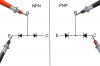
Print out the attached picture and stick it above your bench.
Not sure what you've done so far but start by pulling the big round silver T03 outputs and test them using the picture (the internet will give you EBC). Keep the indicated lead on the BASE and move the other to each of the remaining leads (case is collector).
If you don't have a good set of Pomona mini grabbers I'd order a pair for the next step.
Take your time, NEVER assume and read lots of threads by the smart people here.
Not sure what you've done so far but start by pulling the big round silver T03 outputs and test them using the picture (the internet will give you EBC). Keep the indicated lead on the BASE and move the other to each of the remaining leads (case is collector).
If you don't have a good set of Pomona mini grabbers I'd order a pair for the next step.
Take your time, NEVER assume and read lots of threads by the smart people here.
Attachments
Last edited:

CoreyS
New Member
I tested the T03’s again on the Peak atlas tester and once again they appeared good. But doing the diode test with a DMM the PNPs (H003 & H004) tested bad. NPNs tested good. Looked at your chart again Milo and the black lead goes on the base on PNPs. Retested and the PNPs tested good. I was ready to stop trusting the Peak atlas. Thx! I learned something new.
CoreyS
New Member
The right channel has been the problem. Good idea. I will do a comparison check. Thx.I would start comparing the good channel with the bad one with the meter to look for inconsistencies, assuming that one channel is good.
CoreyS
New Member
Just read EcoWars post from 2005 on testing BJTs. To be clear, when testing the C-E on an NPN the red probe goes on the C and the black probe goes on the E? And vice versa on a PNP? Yesterday I thought it didn’t matter, but was experimenting and got the desired OL one way, but voltage on the opposite way. The B-E and B-C would test good.
Just read EcoWars post from 2005 on testing BJTs. To be clear, when testing the C-E on an NPN the red probe goes on the C and the black probe goes on the E? And vice versa on a PNP? Yesterday I thought it didn’t matter, but was experimenting and got the desired OL one way, but voltage on the opposite way. The B-E and B-C would test good.
Referring to the picture the lead on the BASE stays as pictured for both PNP and NPN and the other lead checks the EMITTER and COLLECTOR. There should be ~.6V for both readings.
Now work your way down the board testing all of the other transistors.
So if they check ok no need to test between emitter and collector?
This is how a transistor is constructed. You can check E>C just to make sure.
Attachments

CoreyS
New Member
I got 2 pairs (H708-H710) L&R channels that failed the diode test so pulled 2 of them (H708 & H710) and they tested good with Peak tester. Been doing continuity checks on row of connectors J710-J722… get a beep between J723 & J726 which are positive and negative so that can’t be right. It doesn’t beep long. Thinking maybe it has to do with a capacitor charging so it stops. Just a guess. I did notice continuity between the 2 orange wires coming from transformer to rectifier. I know it’s AC. Hoping transformer is ok. There’s a small capacitor connecting them.
CoreyS
New Member
Sorry for the long post but I most likely caused some problems and just want to explain things in chronological order. Hope I don’t end up in the Audiokarma hall of shame.
Problems: Relay not engaging / 27 V DC on R Channel / Trimmer R767 Does Nothing
Disassembled P700
1) Replace H706 with 2N3440 hFE=112 (original was 2SD438 E-6H & tested bad)
2) Reassemble P700 & relay engaged for the first time / Medium volume pop in speaker maybe twice in 3 or 4 minutes while playing music
2) While looking at P700 with power on, speakers disconnected and NOT probing, noticed a puff of smoke in the area above J722 & J726 but didn't see resistor damage
Disassembled P700 again
4) Replaced H702 & H704 (2SA763) with KSA992FBU
new transistors hFE = 481 & 472 (this seems off because the hFE seems high & I would have matched the pair better) old transistors hFE = 366 & 243 Old tested good
5) Reassembled P700 and noticed J726 thick red wire had loosened so soldered to J726
6) Began testing voltages - may have shorted something while testing voltages with probes maybe +35 to -35 / maybe R760 to J722
2 resistors show damage but test ok (R731 & R763)
H706 tested bad
J722 burned under circuit board
Disassemble P700 again
7) Tested H004 as J722 Connects to Emitter/ Tested Good
8) Replaced H706 again & all Electrolytic Caps (the caps…presuming this would be the last time the P700 was apart)
9) Replaced Resistors R731 33 ohm & R763 22 ohm (Both 1/4 watt)
Old were burned but tested good 34 ohm & 23 ohm
10) Reassembled P700 and began Testing voltages / No voltage on J729 & J730 / Discovered loose thin red wire from P800 J804 to P700 J729 (35 V DC) / soldered in place & used heat shrink
11) Set DC Offset to 0 & adjust bias to 8 mV DC (original problems of 27 V DC on R channel & inability to set bias now resolved)
12) Relay engaged & music played but R. channel had intermittent pop & sounded poor compared to L. Channel
13) Power up the next day and tested emitter on H706. Puff of smoke & burned same 2 resistors & H706
14) Then discovered loose black wire & traced to speaker selector board (JT15).
Connected to P700 J723 (Ground).
Disassembled P700 again
15) Replaced resistors R731 33 ohm & R763 22 ohm (both 1/4 watt)
16) Replaced H705 & H706 with KSC2383Y / H705 tested good but H706 tested bad
(originally H706 was a metal top transistor like a 2N3440
& H705 was a 2SD438 / hFE=108)
17) Reconnected black ground wire coming from PT01 JT15 to J723
18) Remove frayed wire from chassis to J723 / made a new one & soldered in place
19) Tested output transistors again & all tested the same as earlier:
TOP R H004 PNP hFE = 95 A757
R H002 NPN hFE = 41 C897
L H003 PNP hFE = 99 A757
BOTTOM L H001 NPN hFE = 66 C897
20) Checked fuse & it was good BUT it is a 4A 32V and should be 4A 250V)
21) Using DMM in diode mode tested all transistors
22) 4 transistors H707, H708, H709 & H710 failed the diode test so pulled H708 & H710 R channel which is the problem side) & tested with Peak atlas tester & they tested good (H708 2SC735 hFE=176 / H710 2SA733 hFE=153)
23) Did a continuity test on connector pins at bottom of circuit board & they seem very wrong
J21, J22 & J23 connect
J723 & J726 connect
J714, J716, J718 & J725 connect
J713, J715, J717 & J724 connect
Problems: Relay not engaging / 27 V DC on R Channel / Trimmer R767 Does Nothing
Disassembled P700
1) Replace H706 with 2N3440 hFE=112 (original was 2SD438 E-6H & tested bad)
2) Reassemble P700 & relay engaged for the first time / Medium volume pop in speaker maybe twice in 3 or 4 minutes while playing music
2) While looking at P700 with power on, speakers disconnected and NOT probing, noticed a puff of smoke in the area above J722 & J726 but didn't see resistor damage
Disassembled P700 again
4) Replaced H702 & H704 (2SA763) with KSA992FBU
new transistors hFE = 481 & 472 (this seems off because the hFE seems high & I would have matched the pair better) old transistors hFE = 366 & 243 Old tested good
5) Reassembled P700 and noticed J726 thick red wire had loosened so soldered to J726
6) Began testing voltages - may have shorted something while testing voltages with probes maybe +35 to -35 / maybe R760 to J722
2 resistors show damage but test ok (R731 & R763)
H706 tested bad
J722 burned under circuit board
Disassemble P700 again
7) Tested H004 as J722 Connects to Emitter/ Tested Good
8) Replaced H706 again & all Electrolytic Caps (the caps…presuming this would be the last time the P700 was apart)
9) Replaced Resistors R731 33 ohm & R763 22 ohm (Both 1/4 watt)
Old were burned but tested good 34 ohm & 23 ohm
10) Reassembled P700 and began Testing voltages / No voltage on J729 & J730 / Discovered loose thin red wire from P800 J804 to P700 J729 (35 V DC) / soldered in place & used heat shrink
11) Set DC Offset to 0 & adjust bias to 8 mV DC (original problems of 27 V DC on R channel & inability to set bias now resolved)
12) Relay engaged & music played but R. channel had intermittent pop & sounded poor compared to L. Channel
13) Power up the next day and tested emitter on H706. Puff of smoke & burned same 2 resistors & H706
14) Then discovered loose black wire & traced to speaker selector board (JT15).
Connected to P700 J723 (Ground).
Disassembled P700 again
15) Replaced resistors R731 33 ohm & R763 22 ohm (both 1/4 watt)
16) Replaced H705 & H706 with KSC2383Y / H705 tested good but H706 tested bad
(originally H706 was a metal top transistor like a 2N3440
& H705 was a 2SD438 / hFE=108)
17) Reconnected black ground wire coming from PT01 JT15 to J723
18) Remove frayed wire from chassis to J723 / made a new one & soldered in place
19) Tested output transistors again & all tested the same as earlier:
TOP R H004 PNP hFE = 95 A757
R H002 NPN hFE = 41 C897
L H003 PNP hFE = 99 A757
BOTTOM L H001 NPN hFE = 66 C897
20) Checked fuse & it was good BUT it is a 4A 32V and should be 4A 250V)
21) Using DMM in diode mode tested all transistors
22) 4 transistors H707, H708, H709 & H710 failed the diode test so pulled H708 & H710 R channel which is the problem side) & tested with Peak atlas tester & they tested good (H708 2SC735 hFE=176 / H710 2SA733 hFE=153)
23) Did a continuity test on connector pins at bottom of circuit board & they seem very wrong
J21, J22 & J23 connect
J723 & J726 connect
J714, J716, J718 & J725 connect
J713, J715, J717 & J724 connect
Similar threads
- Replies
- 14
- Views
- 6K


