I could use some help with my amp rebuild and troubleshooting. I have a Marantz 2245 Serial Number 31730. recently I've noticed diminished audio quality on the right side. I've been able to determine it is the p750 board.
For background I've used the rebuild kits from peace.love.and.music of Ebay to replace components on power supply board, both p750 boards. I also replaced the output transistors with MJ21193G & MJ21194G from the same vendor. All components tested OK and well. Left side p750 board sounds great (although I can't still adjust idle current, another issue after I fix the right side, I suspect the original output resistors, yes using the corrected test location).
Right side board is what sounds terrible. I gave this a bit more work, checking for the usual lifted traces, etc.. I've also gone ahead and replaced the variable resistors (R 762 and R 763), I also pulled and replaced the ASO resistors (R794 and R795) (one measured below spec). The output resistors R788 and R789 were just above spec (~.3ohms so also replaced these guys). Board rail voltage measures right about 37volts, so I think I have clean power coming in.
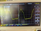
I got my hands on a scope and with a load on speakers, I see a nice notch in the center of the 1kHz sine wave, which tells me something isn't working. My first thought might have been the ASO crossover, but I'm not sure that's the case or not.
I am looking for some advice on my next approach, as I've pulled a leg on each resistor to confirm function, and pulled and rechecked a bunch of stuff on the board with no smoking guns.
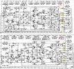
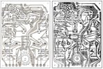
Some pictures attached below. I have done some searching and reading on the forum with marginal success, but I'm at wits end and hoping that one of you guys might point me to how to use the scope and/or voltage testing to properly adjust and get my sweet sound back. Pictures of the board are attached.


For background I've used the rebuild kits from peace.love.and.music of Ebay to replace components on power supply board, both p750 boards. I also replaced the output transistors with MJ21193G & MJ21194G from the same vendor. All components tested OK and well. Left side p750 board sounds great (although I can't still adjust idle current, another issue after I fix the right side, I suspect the original output resistors, yes using the corrected test location).
Right side board is what sounds terrible. I gave this a bit more work, checking for the usual lifted traces, etc.. I've also gone ahead and replaced the variable resistors (R 762 and R 763), I also pulled and replaced the ASO resistors (R794 and R795) (one measured below spec). The output resistors R788 and R789 were just above spec (~.3ohms so also replaced these guys). Board rail voltage measures right about 37volts, so I think I have clean power coming in.
I got my hands on a scope and with a load on speakers, I see a nice notch in the center of the 1kHz sine wave, which tells me something isn't working. My first thought might have been the ASO crossover, but I'm not sure that's the case or not.
I am looking for some advice on my next approach, as I've pulled a leg on each resistor to confirm function, and pulled and rechecked a bunch of stuff on the board with no smoking guns.
Some pictures attached below. I have done some searching and reading on the forum with marginal success, but I'm at wits end and hoping that one of you guys might point me to how to use the scope and/or voltage testing to properly adjust and get my sweet sound back. Pictures of the board are attached.