• The move to the new server is done. There are some software and database maintenance updates in process. This has us passing the hat around to help out. We appreciate any donations. Seriously, even a dollar helps. The payment page may be found here - https://www.audiokarma.org/support.html

Marantz 2245 p750 Board Help

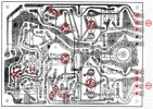
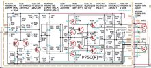
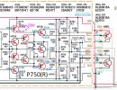
Ok, so I think that I have the schematic and board P750 board layout that matches yours.
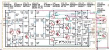
  • I have also marked your measured voltages at the pins for both the R (bad) channel and L (good) channel.
  • Added the voltages you measured for H756/H758.
  • I think it's the negative side of the waveform that is bad so I would start by measuring transistor ECB for H757/H759 to start.
Please also confirm that you have the PNP transistor in socket J015 and NPN in socket J014.

Screenshot 2025-11-02 170521.jpg
Screenshot 2025-11-02 164539.jpg
 
Last edited:
  • Like
Reactions: mbz
Please check these voltage measurements. It looks wrong because the +36.1v becomes negative in a couple of places. (See blue and pink arrows)
Are you sure that you measured the voltages for H756 & H758 from the correct transistors and not H757 & H759?

Screenshot 2025-11-02 193443.jpg
 
Last edited:
OK let me reset, i appreciate everyones help here, this is much appreciated, i measured correct ebc location but reported back incorrect component IDs, during my reinspection i did find a bad solder trace on H758 e, after reflow and remeasure i am getting the following:
H759 e/5mV , b/11.27V, c/-35.79V
H757 e/-34.7V, b/-34.7V, c/11.29V
H758 e/7.4mV b/2.1V, c/36V
H758 e/2.1V b/34.7V, c/35.36V

Also confirmed H001 is NPN and H002 is a PNP.

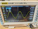
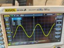
Finally my reflow of the H758 seems yo have smoothed out my sine wave, but still notched.1000014945.jpg
 
H758 e/7.4mV b/2.1V, c/36V
H758 e/2.1V b/34.7V, c/35.36V
Which is the correct transistor voltage and what are the other voltage measurements from?
Also confirmed H001 is NPN and H002 is a PNP.
According to the schematic, H001 is a PNP (SJ2514) and H002 is an NPN (SJ2513).
Did you make another mistake?

Screenshot 2025-11-03 173503.jpg

As for the crossover distortion (distortion at the point where the positive signal crosses the 0v point to a negative signal) you see on your scope.
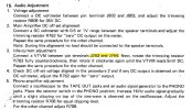
Have you performed the 1st 4 steps below to adjust the DC Offset, and Idle Current adjustment?

(Note: I think there is an error one where to place the meter probes to adjust idle current.)
*** Read this post: ***
https://audiokarma.org/forums/index...g-bias-and-offset-on-2245.538601/post-7030814

Screenshot 2025-11-03 184444.jpg
 
Last edited:
I’m watching this with great interest because I have a 2245 that I bought a rebuild kit for a few years ago. The unit seems to still be performing well and I’ve replaced a few caps on a couple of the smaller boards but it was so long ago I don’t recall which ones. I have some experience with components, schematics and such but can solder like a madmo due to working at a large electronics firm back in the day. My goal is to rebuild it some day. The poster here has way more experience than I do but that’s what makes this so interesting to me.
Dankik, you are obviously an expert in this arena and the fact that you share that with others is great. Just wanted to give you and PAZee a shout out from a rookie with the same unit.
 
Again apologies, I had a typo there here are the correct outputs and labels.

H759 e/5mV , b/11.27V, c/-35.79V
H757 e/-34.7V, b/-34.7V, c/11.29V
H758 e/7.4mV b/2.1V, c/36V
H756 e/2.1V b/34.7V, c/35.3V

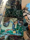
Also yes i mis reported the H001 and H002 because the wires cross over each other, see the picture.
1000014948.jpg


(The previous transistor measurements i grabbed and reported on the h757 and h759 values because i was inspecting from the bottom aide of the board, but looking at the topside layout)

I have done the dc offset and can adjust to zero. Bias adjustment does does not do anything. Measuring .2mV across j754 and j760.

I will investigate the link and report back. Thanks
 
H756 e/2.1V b/34.7V, c/35.3V
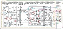
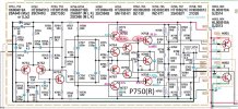
Updated your reported voltages on the schematic.
Again, I think you made an error reporting the H756 voltages.
E = 35.3V, B = 34.7V, C = 2.1V (swapped E/C voltages?)
Please verify.

Screenshot 2025-11-03 220519.jpg

Measuring .2mV across j754 and j760.
Is this correct? You measured 0.2mV from J754 to J760 and you could not get it to 10mV by adjusting R763?
 
Last edited:
  • Like
Reactions: mbz
H757 Vb = Ve suggests possible short?
Also H759 Vbe = 11V indicates possibly open, something wrong in this area, suggest diode test both.
 
Thanks guys for the suggestions, it took a bit to get back to my bench this week.

answering @dankik post:

Verified H 756 as E=12.5 V b= 33.9V and C =34.5V. (see my next values after replacing H759)
correct that I measure basically 0 mv at J754 to J760. adjusting R763 has no effect.

answering @mbz
I pulled H757 and tests OK, NPN hFE=120, Ie=093mA, and Ube=588mV.
Pulling H759 I get a unknown/damaged part. I pulled and replaced this and remeasured the voltages.

my new numbers are as follows:
H759 e/5mV , b/9.37V, c/-35.7V
H757 e/-34.67V, b-35.3V, c/9.37V
H758 e/4.7mV , b/10.6V, c/35.2V
H756 e/10.6mV , b/34.7V, c/35.4V
 
Also H759 Vbe = 11V indicates possibly open
Apologies, this was an error on my part. It's a pnp type so 11V on base is ok/reverse biased.
Good that you fould faulty device, will check latest measurements

my new numbers are as follows:
H759 e/5mV , b/9.37V, c/-35.7V
H757 e/-34.67V, b-35.3V, c/9.37V
H758 e/4.7mV , b/10.6V, c/35.2V
H756 e/10.6mV , b/34.7V, c/35.4V

H759.
Wanting to see base at about -0.6V, someone is dumping +9.37V there, can't blame H759.
Source probably from H758b, H761,R763..

H757
Wanting Vb > Ve
Measurements show Ve(-34.67) > Vb (-35.3)
Suspect a measurement error identifying b, e.

H758
Wanting to see Vbe at about 0.6V, it's showing 10.6V suggests it's failed

H756
Ve can't be 10.6mV suggests R773 is failing/drifted very high.

Inspect R773 for signs of heat stress, try measuring in circuit.
Test H785. H758

Seems you fix/replace one component and somewhere else another one blows...
 
Last edited:
Also, it looks like you have a measurement error: H756(c) = 35.4v, H758(b) = 10.6v, but they should be connected?

Screenshot 2025-11-10 074928.jpg
 
1000014965.jpg
Ok H758 was toast, ive replaced and getting closer to solving this. Many thanks but i still need advise. So crossover doesnt look too bad now on the scope, but audio is still not sounding great and i still cant properly adjust idle current (measuring 0- 0.2mV)

Heres my revised measurements:
H759 e/11.5mV , b/-356mV, c/-35.5V
H757 e/-35V, b-34.6V, c/-360mV
H758 e/11.5mV , b/383mV, c/35.5V
H756 e/373mV , b/34.5V, c/35.1V
 
H756 e/373mV , b/34.5V, c/35.1V
I think that you have an error in reporting your voltages in the post above.
Screenshot 2025-11-11 154800.jpg

I believe there is an error for some versions of the 2245 (see below).
I think you should connect your DMM to J754 and J760 and adjust for 10mV DC.
Please double check this. Here is what I found online.
Screenshot 2025-11-11 154455.jpg
 
1000014995.jpg

Sooo...yes H756 e and c were flipped.
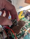
Yes i have been testing at the correct points j754 and j760, but....! I have had this thing apart so much that i didnt have the screws connecting the collector to the leads(see picture), once i did this BAM! I could properly adjust my crossover voltage. Rookie mistake on my part.

Thanks everyone, i am hoping to safely screw this thing back together and be back to listening to some records soon!! Thanks!!
 
Back
Top Bottom