• The move to the new server is done. There are some software and database maintenance updates in process. This has us passing the hat around to help out. We appreciate any donations. Seriously, even a dollar helps. The payment page may be found here - https://www.audiokarma.org/support.html

Marantz 2250B rebuild thread

goldswimmerb

Failed out of engineering, but look at me now!
Subscriber
Hey guys, figured I would post another rebuild thread since they seem to be taken well.

Today's thread is for my ongoing project of a 2250B I got off of that one auction site listed as a parts unit, which is always fun.

My goals for this unit are to get any known bad transistors out of there, replace all electrolytic capacitors and make upgrades where possible, get rid of any VD 1212 diodes, and clean the damn thing up.

Looks like it was stored in a garage for years as I've found a few dead roaches and a whole dead spider that had made it's home in the dial.

The whole inside is filthy as well.

Obligatory Pre Rebuild photos:

fAXPA84.jpg

Faceplate is fairly clean.
kXUkGpT.jpg

AWESOME! Came with the web and the spider!

Preliminary test notes:
All inputs except phono work fine.
Phono is crackly, likely due to the renowned 2SC458 transistors and the 1344s. Betting this is why it was sold for parts.
Volume control is a bit crackly but nothing too bad.
 
Register to hide this ad
That NAD is a pretty baby. I just recently completed a 2250B rebuild so will track this thread and assist if I can. Now get busy!! :D
 
That NAD is a pretty baby. I just recently completed a 2250B rebuild so will track this thread and assist if I can. Now get busy!! :D
Thanks man! I plan to rebuild the NAD at some point, currently also working on fixing a NAD 200 that I royally screwed up on. Ive got way too many amps and nowhere near enough time. Ill be updating the thread shortly with what I've done so far.
 
Most of us do... a disease we all enjoy. :crazy:

Ive got a 2270 that some guy gave up on recapping that is probably going to be an adventure and a huge test of patience (Worked before he redid the PSU and one amp board) now theres no relay click. A Superscope R-1240, a Kenwood KR-5400, A Marantz 2220B, and an Onkyo M-504 all waiting.
 
So far I've done the phono board, tone board and both amps (I started before making the thread)

Phono board (almost done)
IO5KXRK.jpg


Replaced the two tantalum 1UF caps with WIMA films, used nichicon UES capacitors for the 47UF capacitors and upped the filtering capacitor to a 220UF 50v UPW.

I then replaced the two 2SC458s with KSC1845s, I also swapped the 4 2SC1344s (may have been 1345 can't remember, it's been a minute) for 1845s as well to eliminate them as a potential problem. And of course I replaced the VD1212 with two 1n4148 diodes. I'm probably going to go back and replace the two 1UF films on the high pass with WIMAs as well.
 
Be careful with those all plastic 1/4 inch jacks.
:)

Tom
Hey, so I went and redid half of the PSU/RELAY board tonight and my relay no longer seems to engage... Any ideas? (Image attached);

H808 and H807 became KSC2383, as well as H802.
H803 and H805 became KSC945. Voltages all seem to be checking as good? I'm confused now...
 

Attachments

  • IMG_20190926_234553.jpg
    IMG_20190926_234553.jpg
    58.4 KB · Views: 59
Swapped back the 3 transistors in the relay circuit voltages are:

H805
b 167mv/.16v
C 1.15v
E 0

H806
B 1.15v
C .57v
E .56v

h807
B .57v
C .55v
E 0v

J809 and J810 read normally (30mv or so)
 
Last edited:
Put back the KSC2383s and swapped to bipolar caps just to make sure it wasn't a polarity thing. Still no dice... Voltages are off by a bit...
 
Anyone know what the relay closed voltages and open are supposed to be, open and closed? I'm guessing either I messed up a solder connection somewhere or pulled a wire.
 
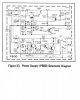
The voltages on the schematic below are when the relay is closed.
It's hard to see the decimal points in the schematic, B of H806 is 1.3V, E of H806 is 0.6V, C of H806, H807 is 0.7V if the offset is OK.
Note that if there is excessive offset from either (or both) power amps then the base of H805 won't be zero volts and the base of H806 won't be positive 1.3V.


Tom
P800.jpg
 
The voltages on the schematic below are when the relay is closed.
It's hard to see the decimal points in the schematic, B of H806 is 1.3V, E of H806 is 0.6V, C of H806, H807 is 0.7V if the offset is OK.
Note that if there is excessive offset from either (or both) power amps then the base of H805 won't be zero volts and the base of H806 won't be positive 1.3V.


Tom
View attachment 1629097
The offset is definitely okay, it's 30mv on both channels.
 
So anyway, still have to sort out my relay debacle, but might as well post what else has been done so far (and worked).

I went through and did the main amplifier boards (and tested them before moving onto the PSU)


m2I1xaL.jpg
went with a WIMA film for the 3.3UF capacitor. Nichicon UKZ for the 47uF + and a lone UFG for the 10uF.

I then swapped out the differential pair for matches KSA992s, swapped the driver? for a KSC2690, and H710 and H711 were replaced, H710 became a KSC945 and H711 became a KSA992.

As always the VD1212s were replaced with the proper dual 1N4148 configuration.

When I have time later I will be working on getting the relay circuit working properly.
 
No, you're a human who made a mistake. Even us "seasoned" techs do!! Glad you found it before going nuts...
 
Almost went nuts there, 1am panic attacks are not fun
It's never a good idea to work when you are tired or upset. Sometimes you just have to walk away and come back later. I can't tell you the number of times I have found the problem in minutes after giving up and coming back later.

I once left a difficult problem for the next day and dreamed how to find it that night!

Tom
 
Alright, so I just finished up the PSU and protection circuit.

Here's the pic:
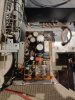
KZyxvGr.jpg


For the relay circuit I left the capacitors all at the original values that were in my unit as I am not super concerned as long as the relay works as it should. I used whatever capacitors I had on hand for that section. The service manual has C807 as 10UF however this unit had a 4.7UF cap there, so I just kept it that value and changed it to a WIMA film.
Normally I wouldn't put a UKZ next to a hot component but it was the only 47UF cap I had that would do the job.

H805 became a KSC945, and H806/807 became KSC2383s.

For the PSU side I had a bit more fun. H803 BECAME A KSC945, H802 became a KSC2383. I then swapped the original DS131-B dual diodes out for two MUR1620CTG ultrafast dual diodes.

I also swapped H804 over to an MJE15030 (way Overkill but the 35v rail is very important) and H801 became an MJE15032 (14v rail). Was confused as the 14v rail is heatsinked (hence the beefier transistor) but the 35v one isn't.

Then it was onto the capacitors, I used mostly UPW caps, but for C806 I used a UKZ As it was the only not 50v+ cap I had.

C801 and C805 were upgraded to 470UF 100V UPW capacitors. (From 220UF and 330UF respectively).

The 35v rail is now spot on.

I did notice that my 14v rail is settling in at around 13.6V, will this be a problem? Seems strange that it is so low (was this way before rebuild too).
 
Last edited:
That +13 supply depends on a sloppy ole zener for the reference. Yours is just fine. The +13 pass transistor H804 has more voltage from collector to emitter so for the same amount of current being supplied as the +35 supply it will run hotter.

BTW, I never turn on and test some newly rebuilt circuitry later in the evening. If it fails I'll either not get to sleep or think about it first thing when I wake up and I'm up for the day then, even if it's 5AM!

@catrafter - I've also dreamed of a solution to a circuit problem and it was the right fix! Better yet, I once was working on a plug in pc board on an extender card and found a bad IC. Desoldered it and replaced it and then noticed it was still powered on. It was then working though! Talk about lucky!
 
Back
Top Bottom