ton4eff
Active Member
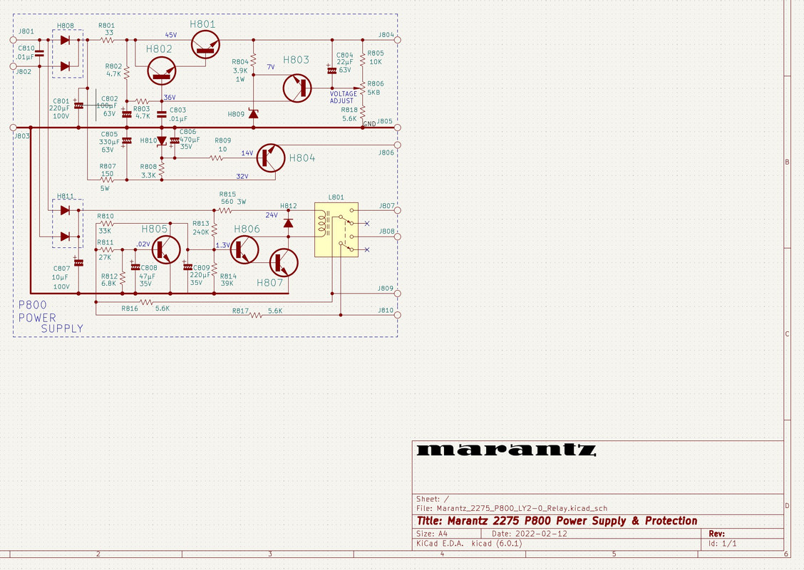
I decided to recreate this PCB. Most probably they use this one in other Marantz models, that I'm not aware of... In the first place, I made a clean copy of the schematic (with the vintage look preserved, of course  ):
):
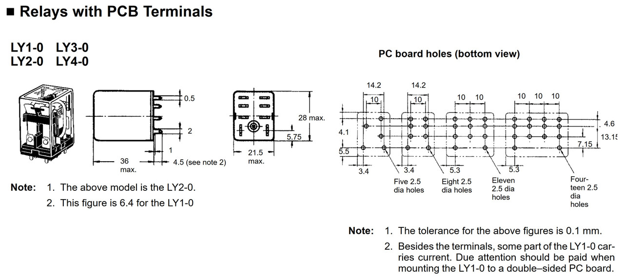
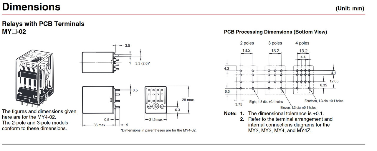
Then, when I was working with the PCB, decided to add an option for installing the higher current Omron LY2-0 relay (10A). I thought it was a good idea at that moment... Or is it? Of course the original MY2-02 (5A) also can be soldered instead. The mechanical dimensions for the relay hole pad's I took from the official datasheets. I hope that they are correct:
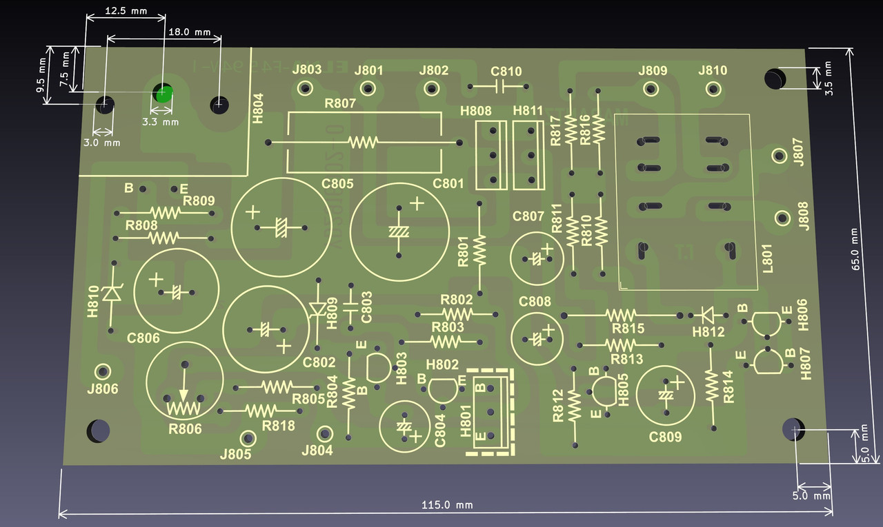
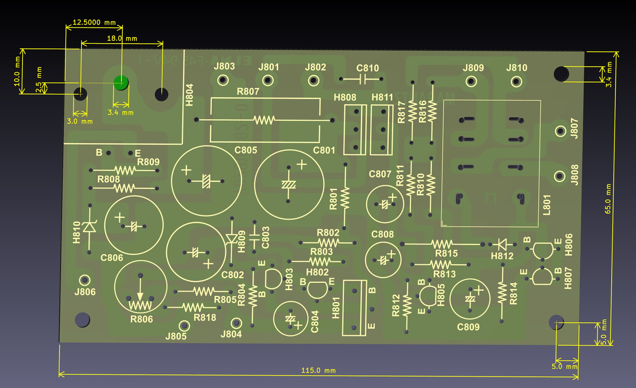
The PCB I copied from the Marantz SM and a couple of pictures from the internet. I was very careful with all the sizes, but it would be great if someone can confirm the mechanical dimensions, especially the part with the H804 heat-sink mounting holes:
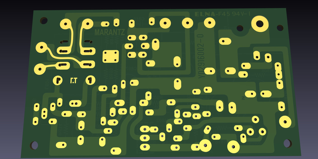
And a look from the bottom side:
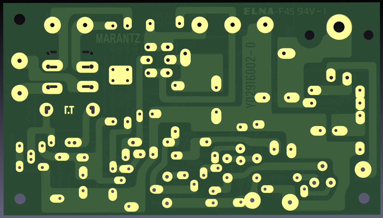
Any suggestions and comments are welcome. Thank you!
):
Then, when I was working with the PCB, decided to add an option for installing the higher current Omron LY2-0 relay (10A). I thought it was a good idea at that moment... Or is it? Of course the original MY2-02 (5A) also can be soldered instead. The mechanical dimensions for the relay hole pad's I took from the official datasheets. I hope that they are correct:
The PCB I copied from the Marantz SM and a couple of pictures from the internet. I was very careful with all the sizes, but it would be great if someone can confirm the mechanical dimensions, especially the part with the H804 heat-sink mounting holes:
And a look from the bottom side:
Any suggestions and comments are welcome. Thank you!


 ). Triple the current is overkill for this vintage design I think. It would require completely modern 2 layer PCB - too far away from the vintage spirit...
  . Actually I may leave only the original MY2 for the final PCB version...
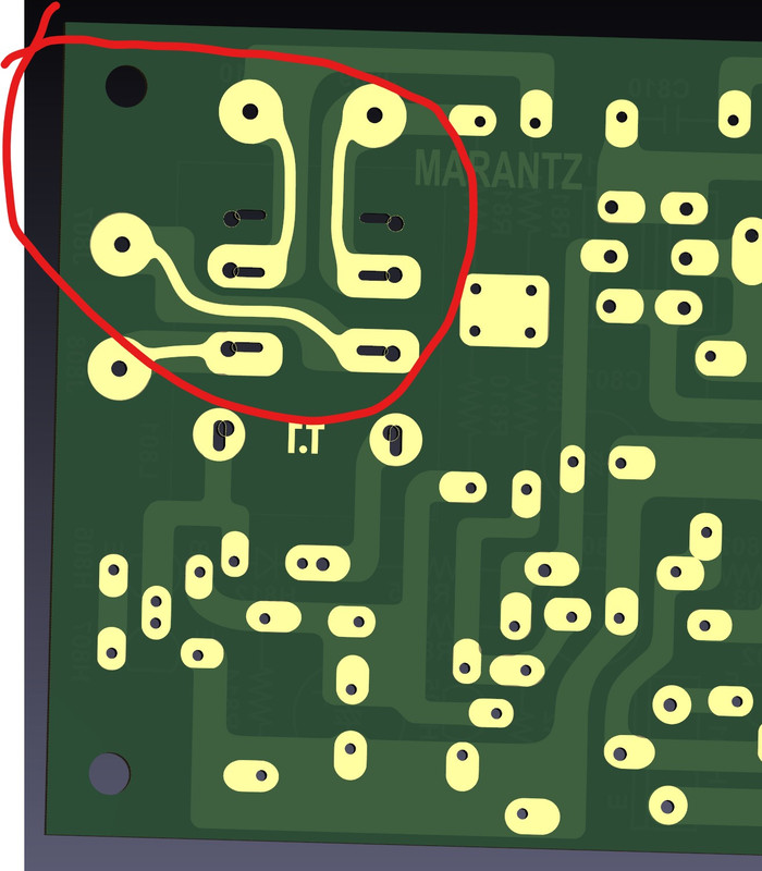
 Just made a small change in the PCB design - added an option for higher current support with this one layer design on the relay speaker traces. Just in case I decide to keep the higher current LY2 -0 relay option. One just have to apply a thicker layer of solder on this relay traces: