• The move to the new server is done. There are some software and database maintenance updates in process. This has us passing the hat around to help out. We appreciate any donations. Seriously, even a dollar helps. The payment page may be found here - https://www.audiokarma.org/support.html

Marantz 2270 P750 Replica Board

R Krawczyk

New Member
Hi All! This is a followup post from a few years ago regarding the work that AK member ton4eff did in producing a replica board for the Marantz 2245/2270 P750 amp boards. You can reference the original post here:
https://audiokarma.org/forums/index.php?threads/marantz-2245-2270-p750-amp-board-replica.844612/

Full disclosure: I'm new to AK (a couple of months). I'm not an electrical engineer and doing vintage restorations is a very new hobby for me! My Marantz 2270 has been with me since 1973 along with JBL L-100s and a Thorens turntable. As one of the last of the draftees, I ended up in Germany in 73 at the right time to buy some nice audio gear in the PX! And yes, that means I'm officially old (turned 70 last week)!

The restoration on my 2270 went very well on recapping all the boards and relamping the lamps with LEDs. But I did run into an intermittent problem with one of the P750 amp boards. Being an amateur, and not wanting to turn my 2270 into a brick, I sent the board to Randy @ irebuildmarantz.com to work on it and see it he can find the problem. He's hard at work as we speak!

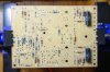
So I started to think about alternatives when I came across the replica P750 board I mentioned above. I found two of ton4eff's boards on eBay and bought both! (see photos).

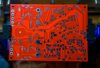

P750 Replica First Look Silk Screen Side small.jpg P750 Replica First Look Solder Side small.jpg

I imagine that many folks would use these boards to replace a damaged board and salvage as many parts from the damaged board as possible. Also, I'm aware that some of the original parts may no longer be available. But what I want to attempt, and what I will be asking all of you in the AK community for help with is to try to populate these replica boards with all new modern equivalent parts to the extent that that is possible.

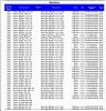
So I did come across some AK threads that had links to Bills of Materials (BOMs) for the capacitors and the transistors as those are generally the parts that get replaced. I didn't find a BOM for the resistors. So I sat down to do the tedious work of building a BOM from Mouser for all the resistors using the Marantz Service Manual.

Being a neophyte I asked several AK members what kind of resistors should I source for this project since most of the original resistors were carbon composition resistors. Basically the consensus was to use metal-film resistors. I also asked if any specific brands were recommended and the consensus was that any of the major brands would be fine. So I fleshed out a BOM for Mouser using KOA Speer resistors for the majority of parts needed and Vishay resistors when the KOA Speers weren't available!

I would be happy to share the file, but I just tried and apparently .xls files are not allowed. Can someone tell me how to share the Parts List and BOM? Thanks. Below is a screen shot of the spreadsheet!

Screen Shot of BOM.JPG

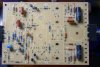
So here's a couple of pics of the board as I began to populate it with parts as they came in from Mouser.
All Metal Film Resistors small.jpg
 
Last edited:
Register to hide this ad
Thanks for this thread. Will be following as I have been eying those boards and interested in hearing how a complete new board sounds compared to an original.

As far as uploading the BOM I think you can only upload a .txt file (possibly for security reasons) or simply copy/paste contents into thread. Then anyone who wants to can copy and insert it into an .xls file on their computer and manually edit columns/rows. Not optimal but seems to be our only option. You could offer to send direct to those that request via PM with email. Perhaps others have found better option.
 
Thanks for this thread. Will be following as I have been eying those boards and interested in hearing how a complete new board sounds compared to an original.

As far as uploading the BOM I think you can only upload a .txt file (possibly for security reasons) or simply copy/paste contents into thread. Then anyone who wants to can copy and insert it into an .xls file on their computer and manually edit columns/rows. Not optimal but seems to be our only option. You could offer to send direct to those that request via PM with email. Perhaps others have found better option.


Thanks JD! At least I'm relieved that I was't too stupid to figure out how to post the file! The future availability of this exact replica board, from ton4eff, might be in question as I think I bought the last two boards from him on eBay. The boards came from Bulgaria where he is from. Perhaps if there is any interest in this thread he might order another batch from the circuit board manufacturer?
 
So I will work on posting the .txt version of the BOM in the near future. I will also send the excel file to anyone who wants it via email. I'd appreciate people's thoughts on the parts list precisely because I'm not in anyway knowledgeable enough to evaluate whether the specific choices are right. First because we all know that the Marantz Service Manual has errors in it. Second, my choices may not be sound from an electrical or physical perspective (especially for the Bourns trimmers at R762, R763 & R794, R795, R796). Third I only created the first part of the BOM on resistors. The second and third parts (Transistors & Capacitors) were already on AK and I just used them. (Already found two discrepancies there: C759 & C760, are 10 uF at 16 V in the Service Manual, replacements in the kit I purchased were 10 uF at 25 V (same as the replacement value on the BOM) but the Mouser part number on the BOM is for 10 uF at 100 V (so I think I purchase the wrong part?). Another mix-up like that is for C761 - SM has 22 uF at 6.3 V, generic replacement on BOM is for 22 uF at 10 V but the kit I bought had 22 uF at 25 V. Which should it be??

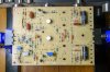
Below is another pic of the board with some additional components on board. I waiting for another order from Mouser, but will be back to this thread in a few days with additional information and questions - thanks!

More Parts 1 small.jpg
 
Going up in voltage ratings for Capacitors is not an issue so long as physical dimensions are acceptable. Also, some voltage values may have been discontinued from earlier cap lists and updated BOMs reflect what’s available.
 
Going up in voltage ratings for Capacitors is not an issue so long as physical dimensions are acceptable. Also, some voltage values may have been discontinued from earlier cap lists and updated BOMs reflect what’s available.
Sure, I understand the flexibility in increasing the capacitors voltage rating. So when the marantz part was 10 uF at 16 V I wasn't surprised that the replacement was 10 uF at 25 V. But the issue is that the spreadsheet calls for 10 uF at 25 V but the Mouser part number was for a 100 V replacement and physically the cap is bigger and crowds the spot on the board. So I think that the 25 V version would be sufficient and fit better? And it is available!

Another question I have about capacitors is that Nichicon will have several caps of the same value, all "audio grade" but of different "series". What's the best series for upgrading these vintage Marantz receivers? There are price differences, but I'd like to know what people think!

Thanks for the info on using Mouser!
 
As jd3rdcoast said It's safe to go with higher voltage for capacitors, as soon as there is enough space to fit. Actually it should be better to go with higher voltage for all the capacitors where it is possible, ESR goes low when they are with higher voltage specs. Are you planning to replace the thermistors H768, 769? I'm sure there is available replacement, but first the thermoprofile should be measured from the originals...

p.s. If the caps meet their electrical specs and do the job as they should, there will not be an audible difference between different cap brands or manufacturers. No matter what some humans say... ;)
 
Last edited:
Ok - attached is an attempt to upload a tab delimited .txt file of the BOM for Mouser containing all the resistors, transistors and capacitors for the 2270 P750 amp board. I don't think it will be pretty so I can PM the excel file to anyone who asks!
 

Attachments

So I've got a few more components on the replica board and I'm waiting for another order from Mouser as well as a couple of parts on back order from them as well.

So here's a pic of the replica board's current state:

More Parts 2 small.jpg

I've got Bourns trimmers in at R762 & R763 (2.2 K Ohms). The zenner diodes are all in as well as the rectifier at H761. The pre-driver transistors are in at H756 (PNP 2N5415) & H757 (NPN 2N3440) (I've got some replacement heat sinks on order from Mouser to hopefully replace the original snowflake heat sinks! Here's the link:
https://www.mouser.com/ProductDetail/532-323005B00

It might be awhile before I have more to report as I'm waiting for both new parts and some original replacements that I may end up having to use!

I was hoping for more interest and participation from AK Forum members, but perhaps it's because of my inexperience at posting to the thread! Any suggestions?
 
:lurk: I think you should keep the original "snowflake" heat sinks if available. They have larger surface, than the mouser ones, which is the most important thing for a heat sink.
 
I'm watching with interest. I have a P750 board that I just can't make work. I plan to do this if ton4eff comes up with another batch of boards.
 
I'm watching too! Just don't have any questions or comments to make. It looks like nice work.
 
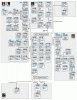
Here is a useful diagram of Nichicon caps types I often refer to. I have some notes on very general rules applied to different applications but the drive I had them on crashed recently. You should be able to do some searches and find many discussions on the subject. LeeStereo’s 2270 rebuild thread is a good reference thread I often turn to.
4ED878C1-4132-4217-A67F-8092A7892209.gif
 
Here is a useful diagram of Nichicon caps types I often refer to. I have some notes on very general rules applied to different applications but the drive I had them on crashed recently. You should be able to do some searches and find many discussions on the subject. LeeStereo’s 2270 rebuild thread is a good reference thread I often turn to.
View attachment 1755891
Thanks - I happened to find this myself last night and I found it useful in understanding and comparing caps of the same rating at Mouser.
 
:lurk: I think you should keep the original "snowflake" heat sinks if available. They have larger surface, than the mouser ones, which is the most important thing for a heat sink.
In principle I understand and agree that the larger surface area on the heat sink is better. If I were populating this board with original vintage parts, (and I know that is how you designed this board for the most part), then I would surely use the original pre-driver transistors 2SA484 (PNP) and 2SC484 (NPN). As far as I can tell, they are not available new anymore. And so for modern replacements I'm using 2N5415 (PNP) & 2N3440 (NPN). I can't find any heat dissipation data for the vintage transistors so I don't know if the original parts needed more heat dissipation than the newer ones? I believe the originals were in a TO-39 package. The replacements are in a TO-39-3 package (not sure of the difference). Also I don't have the new heat sinks yet and don't know if it will fit. If it does, it may be similar to the look of the original and may meet the heat dissipation requirement. Right now it's a crap shoot. Thanks for your input. I'll post some pictures and any additional data on it when I've got something to share.
 
I'm watching with interest. I have a P750 board that I just can't make work. I plan to do this if ton4eff comes up with another batch of boards.
Thanks Steven.

Weren't you a regular contributor to the original thread that ton4eff started as he was designing these replica boards?
 
I'm watching too! Just don't have any questions or comments to make. It looks like nice work.
Thanks - feel free to chime in if I start doing anything stupid! I respect the accumulated knowledge that's here! I need and welcome all the advice I can get. Even though that doesn't mean that I might still go ahead and try something stupid! :)
 
As jd3rdcoast said It's safe to go with higher voltage for capacitors, as soon as there is enough space to fit. Actually it should be better to go with higher voltage for all the capacitors where it is possible, ESR goes low when they are with higher voltage specs. Are you planning to replace the thermistors H768, 769? I'm sure there is available replacement, but first the thermoprofile should be measured from the originals...

p.s. If the caps meet their electrical specs and do the job as they should, there will not be an audible difference between different cap brands or manufacturers. No matter what some humans say... ;)
Thanks, I've a better understanding of what to look for when replacing a capacitor now. Thermistors on the other hand are a mystery to me at this point since, as I repeatedly state, I'm not an electrical engineer. I just got a scrap P750 board for parts from Randy at irepairmarantz.com. It has the original thermistors on it at H769 & H768. How could I measure the thermoprofile on those original parts in order to understand what to look for in a replacement? I appreciated your help - thanks!
 
Weren't you a regular contributor to the original thread that ton4eff started as he was designing these replica boards?
I don't remember if I chimed in on that thread or not, but I remember following it with great interest. He did some very impressive work.
 
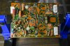
So I've obtained a donor board for some of the spare hard to find parts from my mentor Randy @ irebuildmarantz.com - thanks Randy! I will probably will use several parts from this board, including the wire harness for the main output transistors, some heat sinks, maybe the wire wrap pins, & maybe the thermistors (H768 & H769).

I think I could source new replacements for the thermistors if I knew how to evaluate what were the characteristics of the originals? Other than 21D28 & 150 Ohm I don't know how to measure the thermoprofile of the originals?

And who would have thought that pins would be so difficult to source new? I can't find either of the two styles I've seen on these boards.

Donor Board small.jpg

More Parts 3 small.jpg
 
Back
Top Bottom