• The move to the new server is done. There are some software and database maintenance updates in process. This has us passing the hat around to help out. We appreciate any donations. Seriously, even a dollar helps. The payment page may be found here - https://www.audiokarma.org/support.html

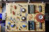
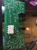
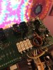
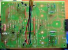
Marantz 2270 P750 Replica Board

This is an interesting idea for a diy pins from a Marantz 1060 pcb rebuild thread. :) Or you can check something similar to these. They should fit in the older type wider pin holes too.
The thermoprofile of the original thermistors can be downloaded with a hot air soldering station and a thermometer. Start with measuring at ambient temperature and check the resistance at a few points with higher temperatures - 30 to 60 deg C. This should give you an idea what modern thermistor replacement to search for.

P.S: I'm sure that you use only a proper wattage modern resistors, but just looking at those tiny small ones, compared to the original big fat boys, gives me an anxiety... Compare the R790 for example. :idea: For me the size still does matter a lot! Also note that some of the bigger wattage ones are lifted a bit farther away from the PCB - better cooling and preventing a burnt spot on the PCB if something bad happens... :)
 
Last edited:
This is an interesting idea for a diy pins from a Marantz 1060 pcb rebuild thread. :) Or you can check something similar to these. They should fit in the older type wider pin holes too.
The thermoprofile of the original thermistors can be downloaded with a hot air soldering station and a thermometer. Start with measuring at ambient temperature and check the resistance at a few points with higher temperatures - 30 to 60 deg C. This should give you an idea what modern thermistor replacement to search for.

P.S: I'm sure that you use only a proper wattage modern resistors, but just looking at those tiny small ones, compared to the original big fat boys, gives me an anxiety... Compare the R790 for example. :idea: For me the size still does matter a lot! Also note that some of the bigger wattage ones are lifted a bit farther away from the PCB - better cooling and preventing a burnt spot on the PCB if something bad happens... :)
Thanks for all these tips. I just took a brief look at the 1060 rebuild thread and I will look at that more closely later on. It's of particular interest because it used one of your replica boards just as I'm doing so I'm sure that some of the issues will be similar! Thanks again and I'll double check the resistors! :)
 
I don't trust the modern specs of the modern passive electronic parts very much. I still from time to time measure and compare for example vintage caps with the same specs marked modern ones, including with a famous brands . Vintage ones often win with lower ESR, lower impedance and overall higher built quality. That's why for the modern ones, I always prefer to go with higher wattage resistors, and higher voltage capacitors. And my experience shows that the similar sized ones - vintage or modern, have similar measured by me real specs! I prefer to trust measuring instruments instead of expensive and famous brands. And if you have a laboratory power supply just compare the temperature of the R790 - original and the modern one you use, if loaded with 1W for example... :D
 
Last edited:
To retain the original 'look' it is sometimes necessary to use a new resistor of higher wattage than the original.

Tom
 
I don't trust the modern specs of the modern passive electronic parts very much. I still from time to time measure and compare for example vintage caps with the same specs marked modern ones, including with a famous brands . Vintage ones often win with lower ESR, lower impedance and overall higher built quality. That's why for the modern ones, I always prefer to go with higher wattage resistors, and higher voltage capacitors. And my experience shows that the similar sized ones - vintage or modern, have similar measured by me real specs! I prefer to trust measuring instruments instead of expensive and famous brands. And if you have a laboratory power supply just compare the temperature of the R790 - original and the modern one you use, if loaded with 1W for example... :D
Thanks. I now have a better understanding of how these parts work electronically speaking and where I can make changes from the original specification. I will most likely take that into consideration when I am working on the second replica board. If I can get them both up and running it will be interesting to compare! Thanks again.
 
To retain the original 'look' it is sometimes necessary to use a new resistor of higher wattage than the original.

Tom
Good point - thanks Tom! And as I just told "ton4eff" I will probably incorporate that idea when I'm populating the second replica board that I have. I had no idea that it was ok to make changes like that to capacitors and resistors without affecting the circuit.
 
This is an interesting idea for a diy pins from a Marantz 1060 pcb rebuild thread. :) Or you can check something similar to these. They should fit in the older type wider pin holes too.
The thermoprofile of the original thermistors can be downloaded with a hot air soldering station and a thermometer. Start with measuring at ambient temperature and check the resistance at a few points with higher temperatures - 30 to 60 deg C. This should give you an idea what modern thermistor replacement to search for.

P.S: I'm sure that you use only a proper wattage modern resistors, but just looking at those tiny small ones, compared to the original big fat boys, gives me an anxiety... Compare the R790 for example. :idea: For me the size still does matter a lot! Also note that some of the bigger wattage ones are lifted a bit farther away from the PCB - better cooling and preventing a burnt spot on the PCB if something bad happens... :)
Thanks - I really like the pins that were made for the 1060 project and I think I will give that a try rather than removing the pins from my donor board! Thanks again!
 
So I did follow up on the idea for dyi pins from a Marantz 1060 rebuild. I used 12 gauge copper wire. I needed to flatten the wire in-order to have it fit through the slotted holes drilled for the original pins. I guess I'm happy with the result! See photo of the board with a couple more components added. Most notably the heat sinks for the pre-drivers. They are smaller than I had hoped and definitely smaller than the original "snowflake" heat-sinks. So I will try to obtain some of those originals!More Parts  small.jpg
 
Hi, I saw the flow chart for the Nichicon capacitors a few posts back. I can find a smaller one showing a portion of the information but not that large flow chart that was posted. Can anyone supply a link to the large flowchart? Thanks.

Never mind. Found it in a different Audiokarma post. link below for Nichicon miniature caps.
https://www.nichicon.co.jp/english/products/pdfs/e-alm_mini_daia_c.pdf

And a chart for Nichicon large can capacitors. Might need to click on the Diagram tab.
https://www.nichicon.co.jp/english/products/alm_larg/default.htm
 
Last edited:
I’ve been working on the same thing for a 2330b but unfortunately having issues with no bias on the left channel and burning a resistor on the right channel. Made of 95% all new components. Hm.
 

Attachments

  • FA77310B-EC5C-4902-BC71-FF2CAD92E899.jpeg
    FA77310B-EC5C-4902-BC71-FF2CAD92E899.jpeg
    129.5 KB · Views: 53
  • 1CE31ADF-648B-411A-8032-86CF9E5130A3.jpeg
    1CE31ADF-648B-411A-8032-86CF9E5130A3.jpeg
    111.4 KB · Views: 54
Привет всем ! и чем это закончилось? очень интересная тема!
my refurbished P750 board on my 2270 sounds in a different key than the untouched original on the other side (
 
Back
Top Bottom