• The move to the new server is done. There are some software and database maintenance updates in process. This has us passing the hat around to help out. We appreciate any donations. Seriously, even a dollar helps. The payment page may be found here - https://www.audiokarma.org/support.html

Marantz 2275 power supply question

Steven Tate

CEO Flat Forehead Soc.
i've started a rebuild on a Marantz 2275. Started with power supply P800 board. I have stripped the electrolytic caps and removed the protection relay. There is a TO-220 case transistor on a small heat sink that is a 2SD331. It may have been hot because there is a lot of brown flux or something around the terminals on the bottom side of the board. When I did my 2325, I found a recommendation from Catrafter to replace the pair of these on the PS with MJE15030, which I did and which worked well. Now... at another place on the 2275 board there is a mounted 2SD330 transistor with no heat sink. Doing an AK search, it seems the same MJE15030 is also the substitute for this transistor. So... the question is, is that same transistor a good substitute for both the SD331 and the SD330? And would any of the experienced guys have an opinion whether I should replace them or not? I happen to have a pair of the MJE15030's left over from my 2325 build. I just didn't see any recommendations to replace these in any of the 2275 rebuild threads, but the possible evidence of heating causes me to want to get some good opinions on this. Thanks!
Steve
 
Last edited:
Register to hide this ad
We always replace that 2SD331 with a MJE15030 on the 2275 power supply board.

Bob
Great! How about that 2SD330 (H801)?

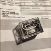
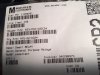
Also, just came across another question. Ordered an MY2-02-DC24 relay, and that is what the Mouser package says. But on the relay, it says MY2 110/120vAC. In the diagram on the case it says 110VAC, 30VDC. The pin arrangement is correct, and it looks like the 24VDC MY2. This relay should work, shouldn't it?
 
Great! How about that 2SD330 (H801)?

Also, just came across another question. Ordered an MY2-02-DC24 relay, and that is what the Mouser package says. But on the relay, it says MY2 110/120vAC. In the diagram on the case it says 110VAC, 30VDC. The pin arrangement is correct, and it looks like the 24VDC MY2. This relay should work, shouldn't it?
If you look on the tape wrapping the coil (inside the plastic case) it better read 24 VDC or 24 DC. Take a peek. I am holding one in my hand . I will add a picture Relay for 2275 .jpg
 
Last edited:
Yes, the H810 can also be the MJ part. The brown crud was most likely heat dried old glue they used to hold it on for wave soldering at the factory. I agree with Beamer on the coil marking. Be sure they sent you the right one or else the driver transistor make go ker-fummmmmp... poof...snap!!
 
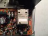
Pics below. The relay has the newer grey cardboard under the plastic, so you can't see the coil directly. I had already mounted the relay, but I'm going to order another one and wait to see if I get a different one before powering up. I really think this is the wrong relay even though it looks just like the old one (other than the grey top) and the pin out is correct. I have already replaced the 2SD331 with an MJE15030, but for now, I think I will leave the 2SD330 unless someone thinks it is just a bad component with a better modern upgrade in the 15030. It's not on a heat sink like the 331, so it likely is OK. Thanks for the responses!
 
The relay has the newer grey cardboard under the plastic, so you can't see the coil directly. I had already mounted the relay, but I'm going to order another one and wait to see if I get a different one before powering up. I really think this is the wrong relay even though it looks just like the old one (other than the grey top) and the pin out is correct.

IMO, you were sent the wrong relay. Measure the coil resistance: the correct DC relay will have a coil resistance of ~640 ohms, the AC relay will have a resistance of ~4.4 kohm. Contact Mouser and they will send out the correct one as a replacement.
 
IMO, you were sent the wrong relay. Measure the coil resistance: the correct DC relay will have a coil resistance of ~640 ohms, the AC relay will have a resistance of ~4.4 kohm. Contact Mouser and they will send out the correct one as a replacement.
Thanks. I will do that. I'm pretty sure this is the wrong one. :beerchug:
 
Mouser is sending out the wrong relays. I just got one from them and it's the same thing. Coil resistance is 4.4K. They are sending out 653-MY2-02-AC110/120. I just contacted them about it.
 
i had a recent one with my supplier rs uk . parts missing in package .. had them flown in overnight from Germany .
was here 11am .. i phoned night before at 10pm ..
 
I didn't bother calling Mouser. I just ordered two new ones to see what I got. They were the correct ones, and I have already installed a new one on the PS board, DBT'd it, fired it up and it easily adjusted to 35V, so on to the filter caps. This will be a little more difficult than the 2325 because the new caps are screw terminal and the old ones were solder lugs. I have disassembled it and am thinking about how to connect the two caps in a way that looks good. The bar that was soldered on the old ones won't work as is because the caps don't come through the chassis holes, and the screw terminals are too short for the bar to reach. I'll have to fabricate something to make it look presentable and still have beefy connections.

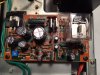
Finished PS board:
IMG_1741.JPG
 
Last edited:
Can you the right Diameter ones??

Otherwise you would have to use a proper fitting length of tubing and longer bolts. Then you could use the plate to link the pos/neg ground.
 
Can you the right Diameter ones??

Otherwise you would have to use a proper fitting length of tubing and longer bolts. Then you could use the plate to link the pos/neg ground.
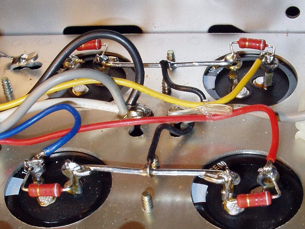
Yeah, the two possibilities I was thinking of was tubing and longer screws or just fabricating a copper plate to fit the screws and ground hole. It turns out that the screw holes on the caps are almost exactly in the plane with the bottom of the chassis. They won't go through the chassis without modifying it, which I don't want to do. But a flat plate with three properly placed holes would screw down perfectly flat. Then I would put ring terminals on the six wires that are soldered to the existing plate and put three on each cap over the plate. The easiest would definitely be tubing and longer screws.
 
...This will be a little more difficult than the 2325 because the new caps are screw terminal and the old ones were solder lugs. I have disassembled it and am thinking about how to connect the two caps in a way that looks good. The bar that was soldered on the old ones won't work as is because the caps don't come through the chassis holes, and the screw terminals are too short for the bar to reach. I'll have to fabricate something to make it look presentable and still have beefy connections...

A simple installation would be to use ring terminals for the screw connections, connected with 10 ga. or 12ga. solid core copper wire.

It would be similar to this installation (note that a ground wire is soldered equidistant from the terminals and connected to the chassis).

Chassis%20Caps3_zpsqfmlekha.jpg
 
A simple installation would be to use ring terminals for the screw connections, connected with 10 ga. or 12ga. solid core copper wire.

It would be similar to this installation (note that a ground wire is soldered equidistant from the terminals and connected to the chassis).

Chassis%20Caps3_zpsqfmlekha.jpg
The difference would be in the screw connections. You wouldn't put that 12 ga wire under a screw would you?
 
Back
Top Bottom