• The move to the new server is done. There are some software and database maintenance updates in process. This has us passing the hat around to help out. We appreciate any donations. Seriously, even a dollar helps. The payment page may be found here - https://www.audiokarma.org/support.html

Marantz 2325 with loud pop after 3 seconds right channel only

FYI - You might want to touch up your solder joints a bit. ;)
Remove solder, clean lead and pad with isopropyl alcohol, heat both lead & pad (at the same time) with soldering iron tip, apply solder, hold for a bit then remove.
You might also want to use some solder flux. Don't forget to clean again with alcohol & Q-tip to remove flux after soldering to prevent board corrosion.
1725035501057.png
1725035692727.png
 
Last edited:
Hi folks,
After replacing the fly-back diodes to J02 and J708 on one channel, it blew the 8 amp fuse. I undid that, place the old diode back. After turning the receiver on, it did nit blew the fuse but the relay did not come out of protection. I check the voltage, it had 110 volts on J809. I disconnected that channel, now it come on and the other channel plays normal.
The p800 board has all normal voltages.
Can we start at the beginning so I can get a better understanding of the board before you started working on it?
Did the board work before you replaced the diodes? Why were the diodes replaced? Originals now back into the board?
Since then, you only replaced the following, nothing else?
Replaced the caps C706 and C707. H701-702 with PNP transistors A722 something...
 
Thanks, dankik! I took a pic different angle, C706-707 solder points are clear.
If I were to check the voltages for H701 - h15 and h001 - h004, and in addition the resisters voltages , I would have to remove the two boards but connect J710 and the boards. Any good suggestion of how to do that safely?
 

Attachments

  • KakaoTalk_20240831_011449425.jpg
    KakaoTalk_20240831_011449425.jpg
    158 KB · Views: 3
  • KakaoTalk_20240831_011449665.jpg
    KakaoTalk_20240831_011449665.jpg
    197 KB · Views: 3
Hi. I don't have a 2325, but looking at the assembly diagram in the SM:
  1. Remove the 4 screws (1920) that attach the L-bracket part of the heat sink to the chassis (shown in yellow)
  2. Move the heatsink with P700 board still attached out of the way so you can get to the connectors at the bottom
  3. There may be two other screws holding a bracket (1913) to support the bottom of the board, but may not need removal
  4. Unplug the audio RCA connector and the Molex power connector.
  5. To separate the board from the heat sink you remove the top bracket and 4 screws (1909) holding the board to the side brackets (shown in blue)
  6. Careful, there will be wires connecting the board to the output transistors.
Maybe someone else that has done this before can assist you better than I, sorry.

But, you don't need to separate the heat sink from the PCB unless you need to remove a component, not to just check voltages.
To check the voltages of the output transistors, they are all wired to the wire-wrap pins towards the bottom of the board. See the schematic to find out which transistor lead they go to. All the pins are labeled with a "J" number for reference.
See photo of separated boards below.

If you decide to power on the receiver with the main amp assembly removed, remember to connect both RCA and power connectors so you get proper grounding. You can also attach a jumper cable between the chassis and mounting bracket.

BE CAREFUL... there are high voltages that can hurt you or damage electrical components if shorted together. Do this at your own risk.

1725296487282.png
1725297530432.png
 
Last edited:
You might be able to use alligator clips or pomona clips (mini grabber) to connect.
1725335566955.png
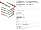
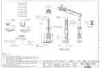
If you can measure the pin diameter you might be able to find the correct size Molex male/female pins.
Solder or crimp one male and one female on a wire, then use heat shrink tubing to cover the exposed part of the connector to prevent shorts and to provide strain relief.
1725335854408.png
1725335910072.png

1725335951254.png
 
Last edited:
Hello! I'm still waiting for some molex parts to connect the power to the amp. I have disconnected both right and left amps from the power and signal path. Now, my question is how hot could the P800 H801 and H802 get.?. when the power amps are not connected at all. I get J804 to J805 voltage of 33v, J804 to J806 18v and J804-J807 13v. What should the voltage between J801 and J802 to J803 be? I checked, it was close 35v
 
Last edited:
Back
Top Bottom