• The move to the new server is done. There are some software and database maintenance updates in process. This has us passing the hat around to help out. We appreciate any donations. Seriously, even a dollar helps. The payment page may be found here - https://www.audiokarma.org/support.html

Marantz 2385 no output on left channel of both Phono 1 and Phono 2

'goodtimes'

Active Member
Hello out there in Marantz land!
I have been working on this beast of a receiver and it has been going pretty well thus far. The original problem was the main filter caps, one deteriorated internally but luckily it didn't take anything out with it. I did my own version of the restuffing them with good results. Once I knew that was all good I proceeded to clean and recap boards. I came across a few issues, but with the help of researching AK I have been successful at getting things resolved without having to ask for help...Which brings me to the point here, Everything is working very well except for the left channel of the Phono section. Both phono 1 and phono 2 have the same issue, no output. I will continue to do my best to trace where the problem is and hope that someone could lend some advice as to what the issue might be. Thanks for all the posts that have helped me on my endeavors thus far and to all future contributors CHEERS!
 
Register to hide this ad
So, I have confirmed that the wires that connect the rca jacks on the rear panel to the connector on the selector/phono board have continuity. The selector switch seems to be functioning properly and has been cleaned. All switches and pots have been cleaned and lubed and operate quietly. If the balance is all the way left and a record is playing I get what sounds like faint bleed through if the volume is all the way up. If I select reverse I get the right channel out of the left speaker, in stereo nothing from the left. Dinner is ready be back later!
 
Well, I am having trouble following the signal on the schematic. If anyone could shed a little light on some areas to investigate I would appreciate it. I think this is the last thing on this receiver that needs to be "fixed". In the meantime I'll keep trying to figure it out.
 
Time for a cheat! On the non-grounded ends of resistors R429 and R430, jumper them and see if you get left channel sound now. If it kills it, maybe the bad channel is shorted to ground. If you now have sound on both, the issue is in the phono preamp circuitry. If nothing changes, I'd be checking the output of the board, after passing through the selector switch. On the board schematic, it looks like that connector is J416 but J414 on the "connection one a few pages earlier! The jumper would go between the end pins of the 3 pin connectors.
 
Time for a cheat! On the non-grounded ends of resistors R429 and R430, jumper them and see if you get left channel sound now. If it kills it, maybe the bad channel is shorted to ground. If you now have sound on both, the issue is in the phono preamp circuitry. If nothing changes, I'd be checking the output of the board, after passing through the selector switch. On the board schematic, it looks like that connector is J416 but J414 on the "connection one a few pages earlier! The jumper would go between the end pins of the 3 pin connectors.
Thank you for the response! I have been busy with family and just checked this and saw you post. I’ll try to get time tomorrow to give your suggestion a try and then report back. Just to be clear, I am jumping from the non grounded end of R429 to the non grounded end of R430?
 
Thank you for the response! I have been busy with family and just checked this and saw you post. I’ll try to get time tomorrow to give your suggestion a try and then report back. Just to be clear, I am jumping from the non grounded end of R429 to the non grounded end of R430?
That's correct. :thumbsup:
 
Ok, When I jumper the non grounded ends of R429 and R430 I get sound on both left and right with the ability to control them with the balance slider.
 
Sounds like one of the preamp circuits on the (nasty) selector boards is out. You can start by grabbing the schematic and parts layout and checking dc voltages from one channel to the other.
 
Sounds like one of the preamp circuits on the (nasty) selector boards is out. You can start by grabbing the schematic and parts layout and checking dc voltages from one channel to the other.
OK, I had it out the other day and lifted one leg of most resistors on the selector board and didnt find any open. I'll see what I can find. Any area you may suggest as a likely problem? We are talking about P400 the Phono Amp/Selector board on the service manual correct? Are there any other boards that may have an issue related/causing this?
Thanks for the help, Hopefully it will help someone else in the future too!!
 
Yes, the P400 selector/phono preamp board. I don't have the feeling it could be anything else. I believe you said the signal was getting there on both channels. We know it's good going forward. The schematic has the dc voltages shown, check those on the bad channel.
 
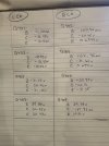
Ok, I did a bunch of measuring of transistors on the P400 Phono/Selector board with no input source connected, volume all the way down, speakers connected but speaker switch off and power on.
there are drastic differences between channels. I am still not sure what is the cause but obviously there is a major issue somewhere. I made a chart with v being VDC and mv being mVDC.


o4FEzlF3R8q+Po866pQMnw.jpg
 
Last edited:
Looks like the emitter is either open on Q401 or not connected, perhaps a cracked trace at the transistor pad. Q403 is whack because of that but looks like the bas to emitter voltage is good, just wrong level.
 
Looks like the emitter is either open on Q401 or not connected, perhaps a cracked trace at the transistor pad. Q403 is whack because of that but looks like the bas to emitter voltage is good, just wrong level.
I suspected a bad transistor or a problem with one of them. I pulled Q401 and Q402 and did the diode test to both and they both have the same readings. I checked continuity on the pad that Q401 shares with 4 other component leads and the trace and pad is good. I am hoping to not have to remove the board again, I worry about the integrity of the plastic connectors and wires breaking. I suppose I'll continue to pull and diode test the transistors on the left channel. If you happen to think of anything else to look into please let me know. And again thank you for taking the time to help.
 
On the negative legs of both C401 and C402 I get a reading of -1.16 mVDC but on the positive leg of C401 I get -1.19mVDC and on the positive leg of C402 I get 27.41mVDC.
I am going to remove and check them both. They both check fine.
 
Last edited:
OK! Progress, after following the bread crumbs I came to Q403 and the E to C diode test failed. I swapped Q403 and Q404 and now my issue is on the right channel. Now to find the correct substitute and get them ordered and see how things look.
 
Great! That would mess things up. Two lists I have say the KSA992 is a good sub. I'd grab ten and replace all of the 2SA872's.
 
Great! That would mess things up. Two lists I have say the KSA992 is a good sub. I'd grab ten and replace all of the 2SA872's.
I had 6 on hand and replaced them and now I get good voltages on that board. In the process of rechecking voltages around different boards I am seeing that my power supply voltages are not matching the schematic. I have replaced all the caps, transistors, and diodes except for Q857. I took pictures before removed any component and was very diligent in orientation of new components and double checked that they were proper replacements. One thing that is throwing me is that upon power up everything is silent and happy aside from the fact that voltages are high some places and low others. None seem extreme and everything plays and sounds right. I measure 38VDC on one side of R863 and it should be 44VDC according to the schematic. If I raise the volume to a decently high volume (1/4 volume or so) I get 43.4VDC but then the transformer starts to have a hum/buzz and it persists even when I turn the volume all the way down and deselect the speakers. If I power the unit off and restart a minute later there is no noise from the transformer any longer...until I turn the music up louder again. If I just play the music at a low volume it is fine. ???
 
+6tI5hUoRumyUZS1qe+uww.jpg
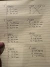
These are the readings I am getting from the power supply transistors. Q854, Q859, Q860, and Q861 all look pretty good to me. Q855 is good at the C, but I think the E and B are wrong. Q856 and Q857 are pretty far off on all legs as far as I can tell from the schematic.
 
Took a look and it seems the schematic is mis-labelled at Q854/5. The "32V" should be 31 and the "31V" should be 31.7V.

The bases of Q856 and 857 should be about 14V to get 13.2V out the emitters. There seems to either be a voltage divider resistor missing on the schematic or Q858 shown as a regular diode is instead a zener and is maybe blown or disconnected like a broken trace or the like. The schem and parts list both claim Q858 is a C945 transistor! Probably it was originally then they did a production change after this schematic.

Okay, I'm out of town until next weekend but will check in when I can on my phone, and not have the SM with me.
 
Took a look and it seems the schematic is mis-labelled at Q854/5. The "32V" should be 31 and the "31V" should be 31.7V.

The bases of Q856 and 857 should be about 14V to get 13.2V out the emitters. There seems to either be a voltage divider resistor missing on the schematic or Q858 shown as a regular diode is instead a zener and is maybe blown or disconnected like a broken trace or the like. The schem and parts list both claim Q858 is a C945 transistor! Probably it was originally then they did a production change after this schematic.

Okay, I'm out of town until next weekend but will check in when I can on my phone, and not have the SM with me.

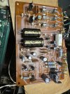
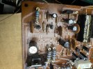
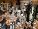
Ok, Q858 is a zeener and every board I have seen online shows the same so I am with you that it was changed after the schematic was drafted. I'll check it again, though I have recapped the board and replaced the zeeners and diodes already, it never hurts to recheck. I hope its just a blown zeener!! I'll follow the traces for the bases of 56 and 57 to see where the voltage goes and hope to find something. Thanks, I'll post my findings. Safe Travels!!o9TZ8dxGRImzv8nbhKmiVA.jpgeu0++uv%TBWyHb185znbLg.jpgBhc8k7WPTHmamRYjDHb1kA.jpg kPcyDRVDR%GAdw009H%Meg.jpg
 
Back
Top Bottom