• The move to the new server is done. There are some software and database maintenance updates in process. This has us passing the hat around to help out. We appreciate any donations. Seriously, even a dollar helps. The payment page may be found here - https://www.audiokarma.org/support.html

Marantz 2500 Refurb

LED lamp replacements

Since ya asked and it was a slow night at the bench, here's how the LED lamps go together / look.

First bus wire is installed and smashed on with some needlenose pliers.
10416057925_a5ded2a4b6_z.jpg


Then solder the wires on.
10416194533_00baa5ec1e_z.jpg


Then the end caps get harvested. I found the easiest way was to make a holder tool by drilling a 1/4" hole (actually 1/64" larger) in a piece of scrap pine. Then desolder the end caps. When they cool, pry the tiny lamp wire loose. Then wiggle the end caps until they come loose. Sometimes the glass envelope broke. Then the crud gets dug out of the ends.
10416192593_3991589c0b_z.jpg


Then slip the cap on and bend the wire over.
10416052725_f6cd559d8e_z.jpg


Solder the end caps and you're done!
10416189153_6cdefc3d80_z.jpg

10416046366_47c84f18d5_z.jpg


I also pulled the fan out and played around with it quite a bit. I figured that the e-clip the holds the rotor shaft on was bumping into the side wall next to it. That was due to it being stretched a bit from popping it loose. I filed the center tab down just a bit so it would go on deeper and filed the open tips just a bit, cleaning it up on the flat side which was to face down. Then I sprung it a bit more closed and got it all reinstalled.

The noise was much lower upon shutoff but the fan had a slight vibration in it and a small amount of rattle while running. So I'm not sure if I tweaked something or it was just getting old and sloppy. I got out the new fan and gave it a test and it was quieter running and shutting down so I went ahead and installed it. The old fan might have been good enough but for how long? It was just not worth it to risk it.

So now I just have to wait... again... for the parts order to come in to finish the last LED lamp.
 
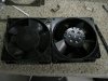
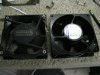
If that's an offer, it's greatly appreciated! If it's a suggestion it's also greatly appreciated!! I used a new Rotron fan I already had but don't know if it's a whisper model or not. It's pretty quiet and a definite improvement over what was in there. What is the model number? I'd like to investigate it in case I ever do another 2500.
 
Sorry all for the lack of updates, it's been a weird week or so and I didn't get out into the shop. I started in on doing rest of the LED conversions: stereo lamp, Dolby lamp and dial pointer lamp. Here it is in pictures.

I solder three T-1 size high efficiency red LEDs together so as to splay out the light better. That is the two end ones are angled out. I did these in parallel which works as long as the LEDs are from the same batch and/or all start turning on at the same forward voltage.
10664059923_f7fd179857_z.jpg


They are taped in place from the top then a touch of medium viscosity super glue is dabbed onto the protruding leads out the top. Once cured, 5-minute epoxy is added to finalize it. I add a piece of frosted lexan right in front of the LEDs to eliminate hot spots.
10663829315_e6b2363e00_z.jpg

10663856256_ae90c75ee8_z.jpg


Here you can see the glued in LED cluster. The white wire goes to the negative side and the red wire is soldered to a current limiting resistor and heatshrink added for insulation. A 1.8K worked well for this. What you don't see is the new vellum paper and dial were reinstalled. I used 1/4" wide double sided craft tape at the top and clear silicone on the narrow bottom ledge.
10663855516_5c48292434_z.jpg


In the last picture and in this one you can see an additional red wire I added for the Dolby LED off to the right. It connects to the +13 volt supply. The stock connection was to the 8VAC which can't be used directly for the LED. I used a hot melt glue to tack the wire down.
10663848956_ffd64f3b9d_z.jpg


The red wire has the resistor added inline and is covered in heatshrink. The black wire replaced a red one for the negative side of the LEDs. That gets grounded by the Dolby plug in module which this unit does not have unfortunately. But if one is ever installed the indicator will match the stereo one on the other side!
10663805705_2e43a79d9f_z.jpg


On to the dial pointer. Here I have pried up the fingers on the carrier housing to get at the innards.
10664034373_f75120ef63_z.jpg


Then the carrier pops off and the bulb is now accessible.
10664029123_e2cf7f486f_z.jpg


The wire for the 8VAC has been removed from JZ01.
10663789385_8dedeff177_z.jpg


That wire will get +13Vdc and the other end at the dial pointer has been marked red with a felt pen.
10664020323_607a38dceb_z.jpg


A T-1 LED has been soldered on. I was going to play with a green one but had forgotten that the top of the clear acrylic pointer is coated with red coloring at the factory. Oh well! Make sure to check the LED is still working beofre the next step.
10663777485_66db5a88af_z.jpg


Slightly out of focus but here the LED has been taped in place and illuminated from the other end of the wires with the DMM in diode check mode. A bit of super glue has been applied at the open end of the housing and the wires and is waiting to set. That's as far as I got and will add epoxy tomorrow and reinstall the carrier back onto the metal shuttle and bend the prongs back. After that I'll show the connections back at the other end on the top left.
10663809286_6c5b588a0f_z.jpg
 
I hustled at home during lunch and got the LED glued in place.

First I taped the assembly relatively level.
10676786923_dfa330fd42_z.jpg


Them mix up some epoxy and dab it in with a toothpic, making sure to get it all the way out onto the wires for strain relief. I'll likely add some more epoxy to the other side of the wires later. The extra epoxy on top will need filed down so it will all reassemble properly.
10676446515_8f6ec786c9_z.jpg
 
The rest of the LED story...

The power source is the red +13 volt wire I ran for the Dolby LEDs. I've cut a bit of the insulation off with an X-Acto knife. Then tinned the wire.
10683725704_781e9a161a_z.jpg


Then a resistor substitution box is clipped in.
10683911793_13982d9211_z.jpg


The selected resistor is soldered onto the "low side" wire that was unsoldered from the 8VAC source the other day. First some heatshrink was slid on, then the resistor was soldered on.
10683660555_b02ba05b45_z.jpg


The heatshrink was slid down and shunk with the soldering iron tip. Then the other end was trimmed to length and bent around the wire opening and soldered. After this picture I mixed up some epoxy and put it all around the lower solder joint to insulate it.
10683701766_79cf254276_z.jpg


Here's the dial all lit up. Most digital cameras don't do blue light well and mine is no exception. It is actually a way more vibrant display. The middle photo is the closest although it is overexposed.
10683703214_bc5ca67ee7_z.jpg

10683695164_a4ca9c5670_z.jpg

10683686414_f1cc232401_z.jpg


OK now it's on to doing the big filter electrolytics. I hope I don't have to tear it all apart again!
 
I got the big double electrolytic filter caps pulled this evening. Mostly this post is to document the removal and connections.

I searched around AK, looking at the restuffing posts. I like the method of prying the end of the can up but on these that would require cutting the outer sleeve and the caps either sit on the chassis or are close to it. Besides, it might look messy! I saw one where a pipe cutting tool was used to open the case and I'm sorry I didn't make note of the person's name that showed that because I like that idea. It would make a nice even square cut. These puppies are 2-1/2" in diameter though and I don't have a cutter that big. Sears claims to have one so I'm going to cruise on over there tomorrow if I can. A Harbor Freight is on the way so I'll stop there first.

OK, here's the photo essay. This view is with the front of the receiver towards the bottom of the picture. The receiver is upside down.
10702146794_ccca92e433_z.jpg

10702143484_5b95159ff5_z.jpg

10702083735_dff422f3cc_z.jpg

10702157966_e417c22bac_z.jpg

10702153466_36dacdc13f_z.jpg


First the wires need removed, I had to get out the soldering gun (140W) to melt the solder. Looks messy, huh?!
10702125324_c79108ece7_z.jpg


The obligatory soda can comparison shot.
10702146296_bb6f435739_z.jpg


Top view - where the caps were installed. Now I can clean that area out a bit better.
10702141156_b2ab6a30e1_z.jpg


Both of the smaller fellas are going into the can. I would have liked the 105 degree rated caps better but they were not in stock. The originals are 85 degree so it's no worse. Stock capacitance is 7200uF and these are 8200uF, about 10% more. I really don't like going any higher than is practical so as to not increase the surge current on the rectifier.
10702133816_824d388ee0_z.jpg
 
First of all...great thread and great work. :thmbsp: I have a 2500 that I have been wanting to do for a couple years, but have been a little intimidated. It's the only one I got. Anyway, I mentioned this in one of the other dual cap threads. I think I would hold out for the higher temp rated caps. It seems to me that the heat factor to the new caps will be multiplied by being stuffed inside a metal can. I dunno how much tho. Something to think about. :scratch2:
As I said before, great work and I like your style.
 
Thanks Yostie! I figured in that the originals were 85 degree rated and that the 2500 is fan cooled so it won't get that hot. Also in real life that for the vast majority of the time the user won't be running it full tilt. Here's the real kicker... where I work we pot a lot of our products in thermally conductive epoxy and I planned to fill the cans as much as possible before final reassembly.
 
Is it necessary to use four smaller caps? Would it be possible to go with two 15 or 22 mF caps instead? Or are we looking at some unusual wiring?
 
Ooh, I just read about this somewhere in AK. Some say it can be done but is dangerous and some say it can't or at leat shouldn't be done. I bet it would be okay if only used with symetrical waveforms, such as a sine wave. But music is anything but so sometimes the negative supply is being asked to source more current than the positive and vicwe versa. So the midpoint "ground" would be floating up and down. OK, I would bet very much on that theory!! But I know if I stick with the original design it will work as designed.
 
Yostie - I looked again today at what caps were available and I now remember the issue. The 125C caps at enough capcitance at a high enough voltage were all too tall to fit two in the gutted case. They were at least 60mm so X2 = 120mm. The old caps were 115mm end to end.
 
I found a pipe cutting tool at Lowe's made by Superior Tool, model ST-2000 for about $20. It barely fits but does the job. The cap wanted to pop out all the time but adjusting the tightness often helped that.
10736599356_51d39284d8_z.jpg

10736503015_b341f175ba_z.jpg


Kind of reminds you of those biscuit containers you smack againt the counter to open, right?
10736803873_87539e1c66_z.jpg


Topless!!
10736585596_20ba453e34_z.jpg


Some Cratsman RoboGrip pliers got the center plug out. It's actually one of the two capacitors. I'm going to use a heat gun as suggested by others to get the outer capacitor loose and pulled out.
10736585244_dc001bd941_z.jpg
 
Yostie - I looked again today at what caps were available and I now remember the issue. The 125C caps at enough capcitance at a high enough voltage were all too tall to fit two in the gutted case. They were at least 60mm so X2 = 120mm. The old caps were 115mm end to end.

Yea, I woulda went for ones that fit also.
:lurk:
 
Hi TMZ, I don't know as I didn't take Mech up on his kind offer. You might try PM'ing him. I had a new unused (but old) Rotron fan so used that.
 
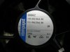
So what was the model number to this fan motor ? Thanks

FYI, EMB Pabst 4606Z is a high quality, all metal, ball bearing, low noise fan that fits with a minor modification to one of the screw brackets.

Tom
 

Attachments

  • 2500 fan (3).JPG
    2500 fan (3).JPG
    80.6 KB · Views: 49
  • 2500 fan (1).JPG
    2500 fan (1).JPG
    103.7 KB · Views: 51
  • 2500 fan (2).JPG
    2500 fan (2).JPG
    103.2 KB · Views: 54
Back
Top Bottom