• The move to the new server is done. There are some software and database maintenance updates in process. This has us passing the hat around to help out. We appreciate any donations. Seriously, even a dollar helps. The payment page may be found here - https://www.audiokarma.org/support.html

Marantz 2500 repair help

quadmatrix82

AK Subscriber
Subscriber
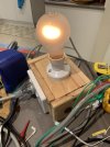
Hi Marantz 2500 experts, I am currently working through repairing my Marantz 2500 and wondering if anyone has noticed how bright the dim bulb runs with a 150 watt globe, my 2500 clocks out of protection but the dim is glowing but wondering if this is normal given it’s high power consumption.

Also has anyone experienced or know why one channel wouldn’t be able to bias below 10mv with the dim bulb? Bias seems steady but I am unable to reduce it below this point, Thanks in advance
 

Attachments

  • IMG_3511.jpeg
    IMG_3511.jpeg
    88.2 KB · Views: 9
Register to hide this ad
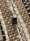
Does anyone know if these look real or fakes? This is the bias transistor 2sc1568r that I bought I have a few T variants on hand but the service manual says on R or S can be used
 

Attachments

  • image.jpg
    image.jpg
    172.2 KB · Views: 31
That’s too bright. Should be nothing or almost nothing.

Probably. Why aren’t you using a BD135 or MJE243?
I just ordered both that you suggested from mouser today to try - need to rule out that these are causing my issues

Thanks, I’m at a loss what could be causing this I’ve gone right through this receiver and see nothing obvious now it’s fully recapped almost all new transistors and all diodes are done and a bunch of other bits
 
If possible, unplug both amp channels and make sure the DBT is nothing. Then plug each one in. See what’s lighting things up.
 
No. If you’re working on this thing, you should know.

From Google, it looks like there’s the signal connector and the power connector. Unplug them both from a channel, DBT, then the other…..
I’ll have a look to see which ones they are and try
 
No. If you’re working on this thing, you should know.

From Google, it looks like there’s the signal connector and the power connector. Unplug them both from a channel, DBT, then the other…..
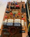
These two right? Plugs removed from the photo
 

Attachments

  • IMG_3531.jpeg
    IMG_3531.jpeg
    147.2 KB · Views: 58
What about both disconnected?
Then you did something wrong in the power supply.
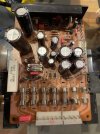
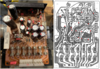
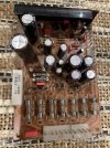
Here is a photo of the power supply board, it has all new caps, transistors, diodes I couldn’t find any shorts on the resistors. The dim appears to be the same brightness with the amp modules disconnected maybe a touch less than before but hard to tell as it’s a frosted lamp and the only one I have.
 

Attachments

  • IMG_3544.jpeg
    IMG_3544.jpeg
    143.2 KB · Views: 28
  • IMG_3545.jpeg
    IMG_3545.jpeg
    104.7 KB · Views: 27
I’m fearing the worse that the transformer is shorted, how would I test this to rule it out? Relays click out of protection still and fan drops to low speed
 
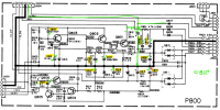
I went thru the schematic, PCB layout, and PL. The only thing that was strange was that the schematic only shows a C812 (10uF) but the board layout and your photo show C811 & C812, but if you look at the PCB, the C812 (-) ONLY connects to C811 (+) which then connects to Q807. What doesn't make sense is when you put two capacitors in series the capacitance value is one-half. So, 10uF x 2 = 5uF??? Is there a jumper wire on the back side of the board that connects to that "island" pad?

The other thing to note is that on the schematic, C810 has its polarity wrong, the (+) should be connected to ground since it is a negative voltage. But, you have it installed correctly.

The other thing I can't see from the photo are the diodes Q810/Q811... are they facing the correct directions?
1721450316633.png
1721450339224.png
 
I went thru the schematic, PCB layout, and PL. The only thing that was strange was that the schematic only shows a C812 (10uF) but the board layout and your photo show C811 & C812, but if you look at the PCB, the C812 (-) ONLY connects to C811 (+) which then connects to Q807. What doesn't make sense is when you put two capacitors in series the capacitance value is one-half. So, 10uF x 2 = 5uF??? Is there a jumper wire on the back side of the board that connects to that "island" pad?

The other thing to note is that on the schematic, C810 has its polarity wrong, the (+) should be connected to ground since it is a negative voltage. But, you have it installed correctly.

The other thing I can't see from the photo are the diodes Q810/Q811... are they facing the correct directions?
View attachment 3255377
View attachment 3255380
Thanks for investigating, if it helps I have a multi voltage model (set to 240v) I believe there are two versions of this board from what i know.

I don’t see a jumper for the caps, i believe I have soldered in the diodes correctly, see pics hope this helps :)
 
Photos
 

Attachments

  • IMG_3548.jpeg
    IMG_3548.jpeg
    123.2 KB · Views: 20
  • IMG_3547.jpeg
    IMG_3547.jpeg
    184.9 KB · Views: 19
  • IMG_3546.jpeg
    IMG_3546.jpeg
    194.9 KB · Views: 20
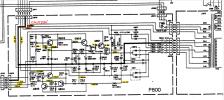
Take caution when poking around on the P800 PCB, looks like some high voltages there. You can check the lower voltages to see if any are off.
1721451950130.png
 
Back
Top Bottom